16bit DAC, Maxim MAX5217
16bit DAC, Maxim MAX5217
With my electronic load, I started with MCP4921, which is nice IC, 12bit DAC, but wasn't good enough.
So I went with 16bit DAC from Maxim, the better option of two, MAX5217GUA+ . I found basic Arduino sketch from EC-Projects, the same one he used in his, which made my work really easy.
Connecting IC:
REF: Here is where you connect your reference voltage, I will go with 4.096v that I get from ARD4540BRZ (BRZ being better grade then ARZ, also more expensive).
ADDR: This is up to you, since this is I2C device, you have two fixed addresses to choose from, depends if you drive that pin LOW or HIGH.
Third option is leave it floating, that is another option.
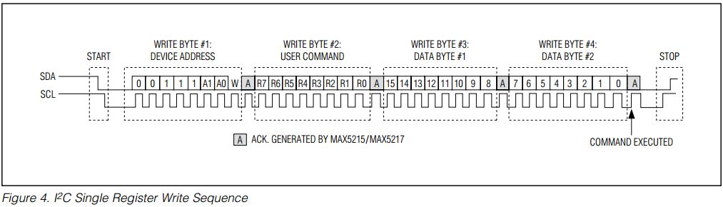
SCL: is your clock line
SDA: is your data line
AUX: with this, you can clear internal registers or if driven LOW, load the CODE register (code that you would like to output next) to DAC register (code that is on output now). I have it low, loads code to output right away.
And you have your OUT and Vdd and Gnd.
Setting registers:
Most of the times, you will use three user write commands, In my case I use only one.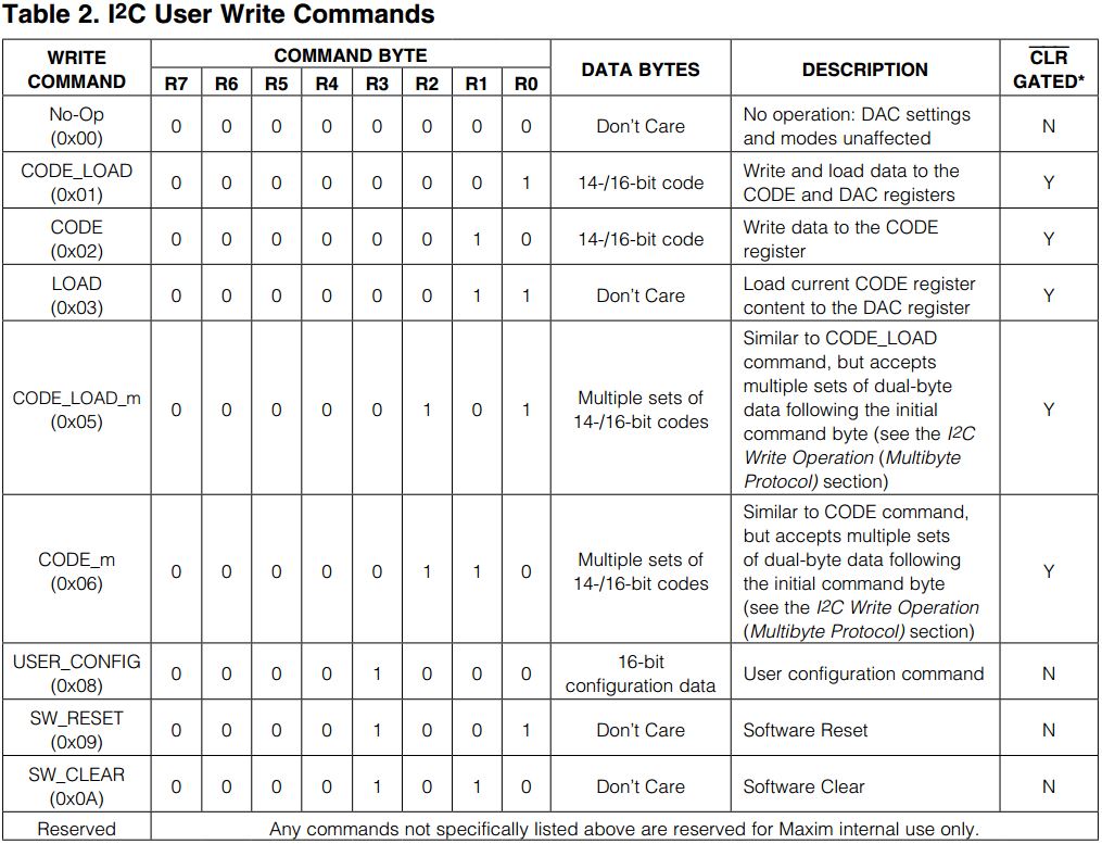
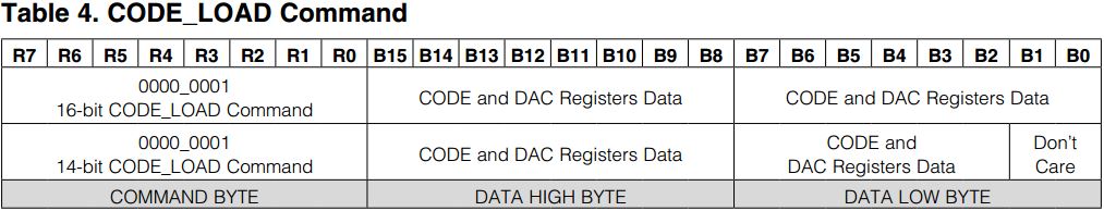
The CODE_LOAD(0x01), which writes and loads data to the CODE and DAC registers. Output changes right away.
Other two are, if you want to have seperated command from above:
CODE(0x02): Write data to the CODE register
LOAD(0x03): Load current CODE register content to the DAC register
And there is also one command used in setup stage of your program:
USER_CONFIG(0x08): This will setup the DAC.
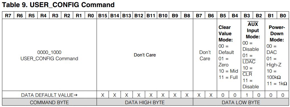
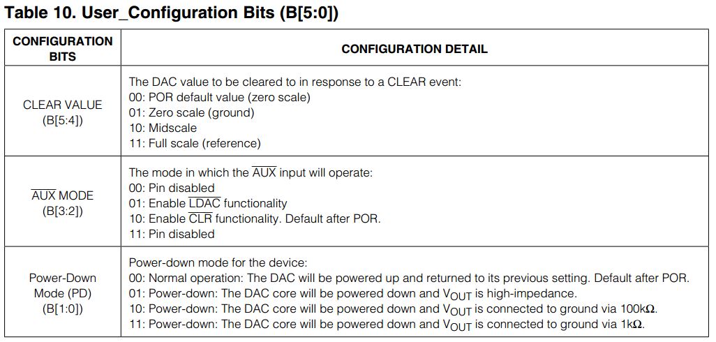
What is default state of output (zero, mid of full output) with bits 4 and 5.
You also tell it, what AUX function will be with bits 3 and 2, I have it disabled.
And last one, in what state is goes in power down mode with bits 1 and 0:
Arduino IDE sketch for max5217
MAX5217 visits: