24bit ADC, AD7780
24bit ADC, Analog Devices AD7780
I received samples from Analog Devices, one of them being 24bit A/D
Looking at datasheet, it is pretty simple device with simple SPI compatible communication.
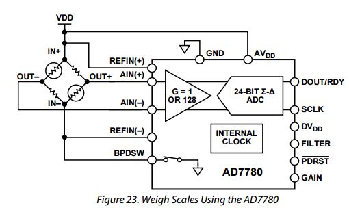
I wired it for non battery operation, by that I mean BPDSW switch was never opened (bridge of load cell always connected, but I don't use it for load cell measurement anyway)
REFIN(+), AVDD, DVDD, FILTER and PDRST were connected to 5v, GND is connected to ground.
There are two options for data transfer (SPI is any other two pins):
SCLK is either pin 12 when connected with SPI, or pin defined in sketch.
DOUT/RDY is either pin 13 when connected with SPI, or pin defined in sketch.
Settings you could change:
GAIN: when low, gain = 128, when high, gain = 1
FILTER: when low, update rate is set to 16.7 Hz, when filter is set high, update rate is set to 10 Hz
PDRST: when low, ADC is powered-down, if set high, ADC is taken out of power-down mode
BPDSW: if you have this ADC battery powered, you can disconnect the measduring bridge (input circuit outside ADC)
DIGITAL INTERFACE:
The DOUT/RDY pin is dual purpose: it functions as a data ready pin and as a data output pin.
DOUT/RDY goes low when a new data-word is available in the output register.
A 32-bit word is placed on the DOUT/RDY pin when sufficient SCLK pulses are applied.
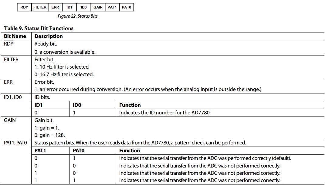
This word consists of a 24-bit conversion result and eight status bits.
Non-SPI sketch uses all 32bits and last 8 are used to see if data is valid.
while(statusBits ^ B01001101) here is where you check for that. In my case you compare it to B01001101.
Arduino IDE sketch SPI alternative
AD7780 visits: