High Power Half Bridge ClassD Amp (Prototype)
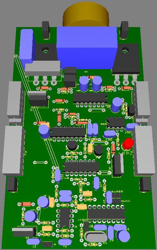
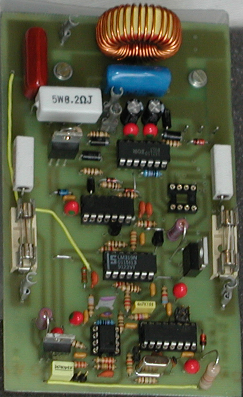
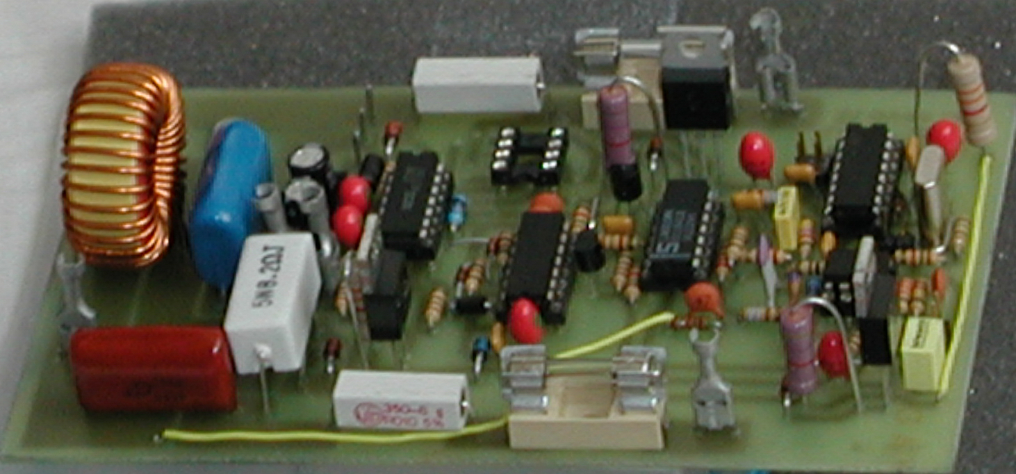
This is how it will look like
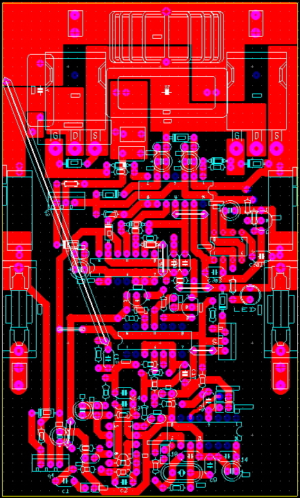
Before eatching...
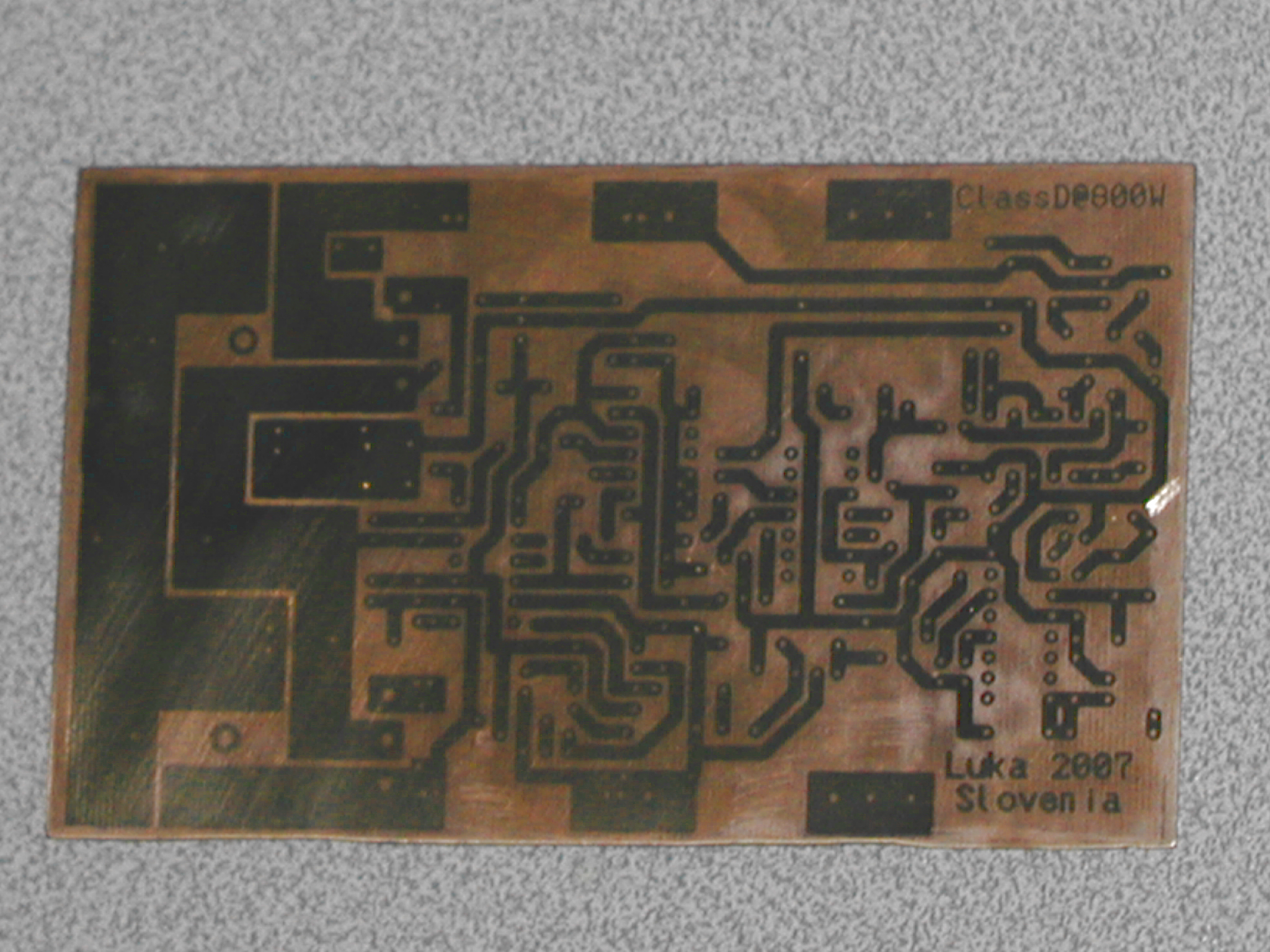
Board after being eatched and ready to put elements on
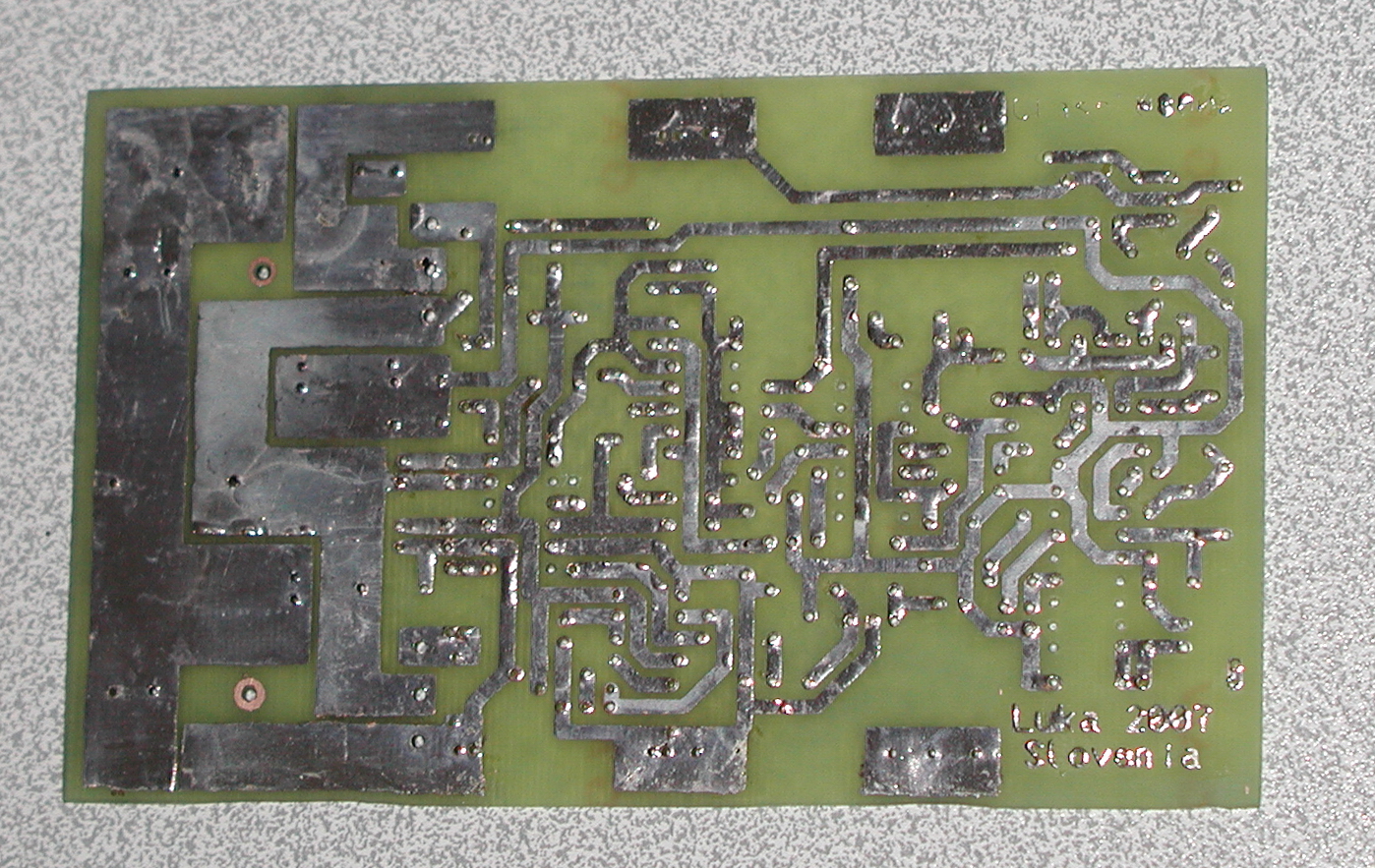
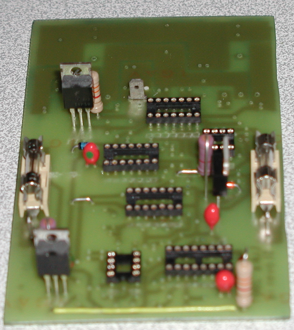
On picture above one can see that one chip is missing.That is overcurrent limit, which becomes active when ther is bigger voltage drop on current sense resistor then set. This activates the timer, which disables output for time that is set by components, which is in my case a bit over 1s. After that output is enabled again.
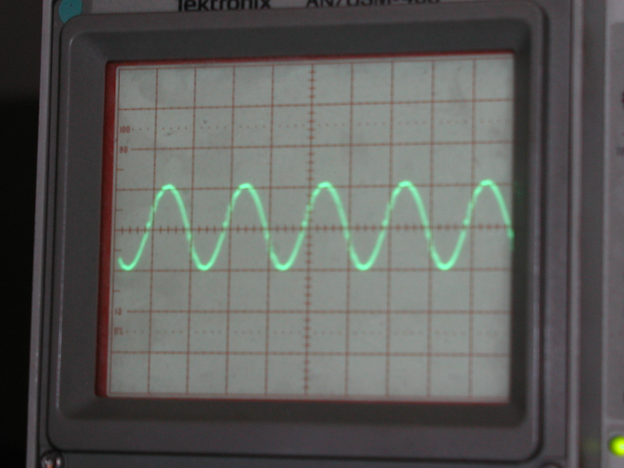
Output ripple @ 250kHz with spikes because of too small cap use to decouple supply.But I have been told that it could be throughshoots (Bigger dead time will be needed). This does NOT effect the sound, but will need to be sorted out for higher efficiency. Sinewave is always present on output in any ClassD amp.This one is 1Vpp and that is small and is dependent on supply voltage, output filter and freq. of the amp.
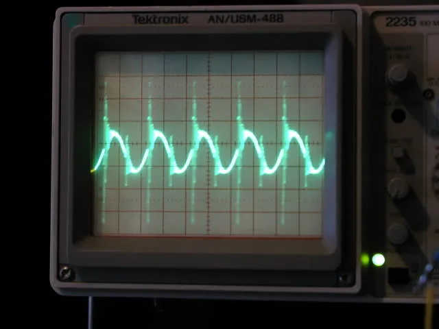
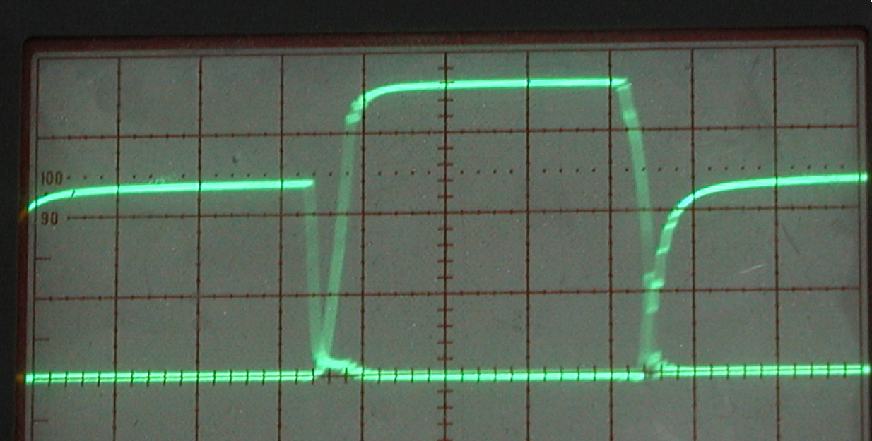
This was caused by usage of wire resistor, which has inductance, that cause this spikes. After swaping them with non-wire ones, this is what came out. Difference is big as seen from pictures above and below
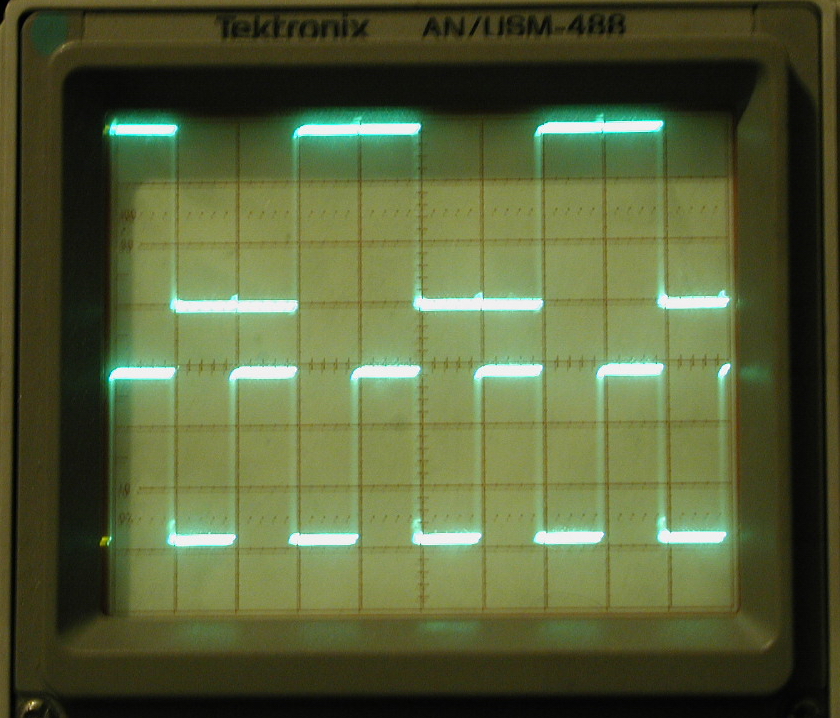
Picture of both gates looking them at the same time. Not the best, but doesn't seem to cause any problems
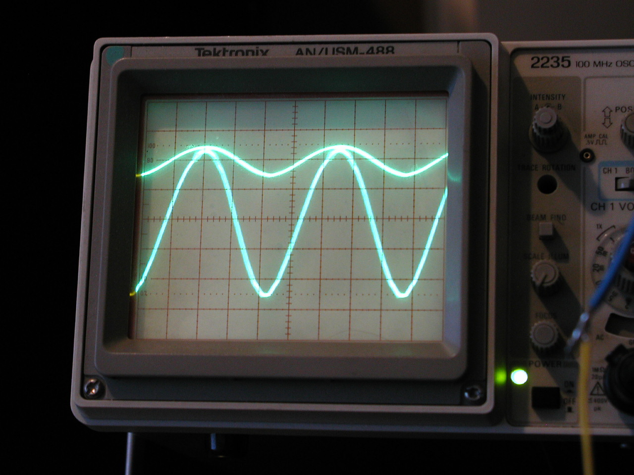
Upper one is input, lower one is output near clipping.
Synchronizing clocks, 125kHz for smps and 250kHz for other amps
Thing to remember:
- Use fast fets, which has small Qg (total gate charge), small Rds(on), but most important small trr (Reverse Recovery Time of diode) and for that matter Qrr too.
- Do NOT use wire wound resistors.
- Use best decoupling capacitor you can find, that you will put cross +Vcc to -Vcc as close to fets as possible
- When testing for the first time you should have adjustable dead time resistors, for setting smallest dead time for your design.
Schematic is here
Next page is problems, solutions and what was wrong.