Repair of Mean Well RSP-2400-24I bought off Ebay one of this high power switch mode power supply, which was advertised as being broken and sold as not working. Got it out of the box, put if on bench, hooked it up to supply and... sure enough, it was conducting current at very low voltage for input to power supply. 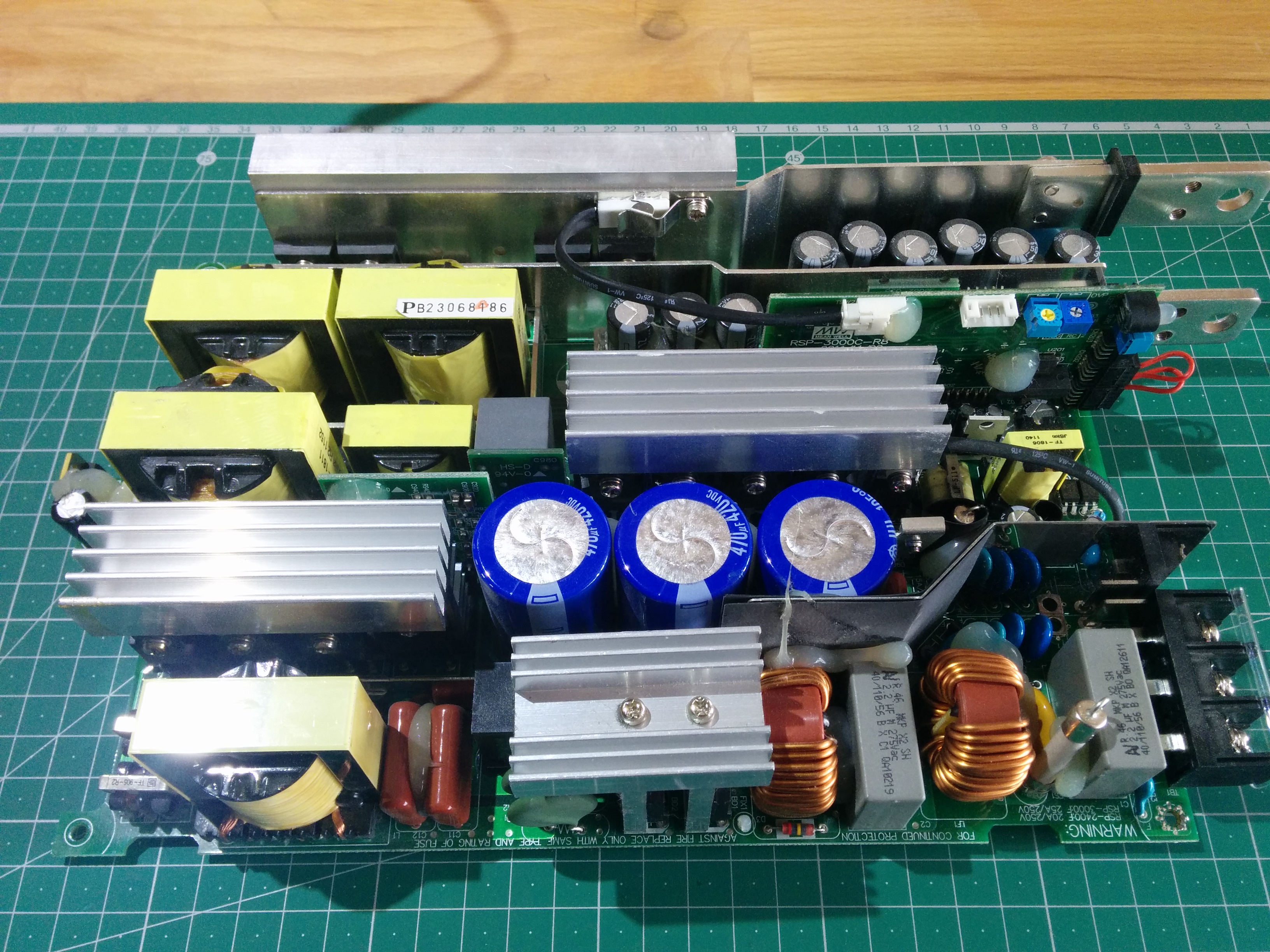
Looks so small, wouldn't have guessed that this can do more then 2400w on output! Let me take some time and explain where is what.
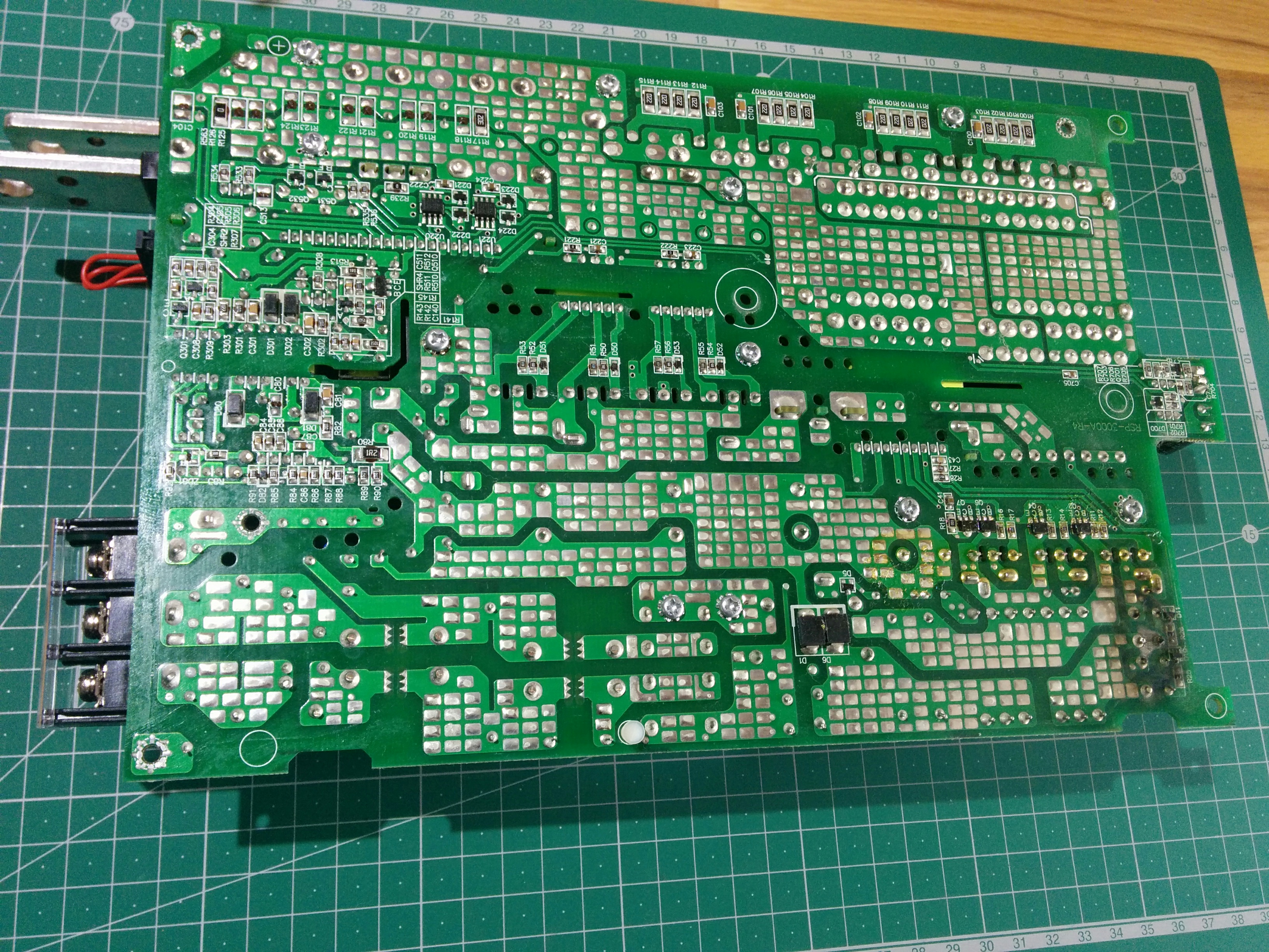
Turning it upside down, to check if anything can be seen from here. Layout is nice and simple to understand.
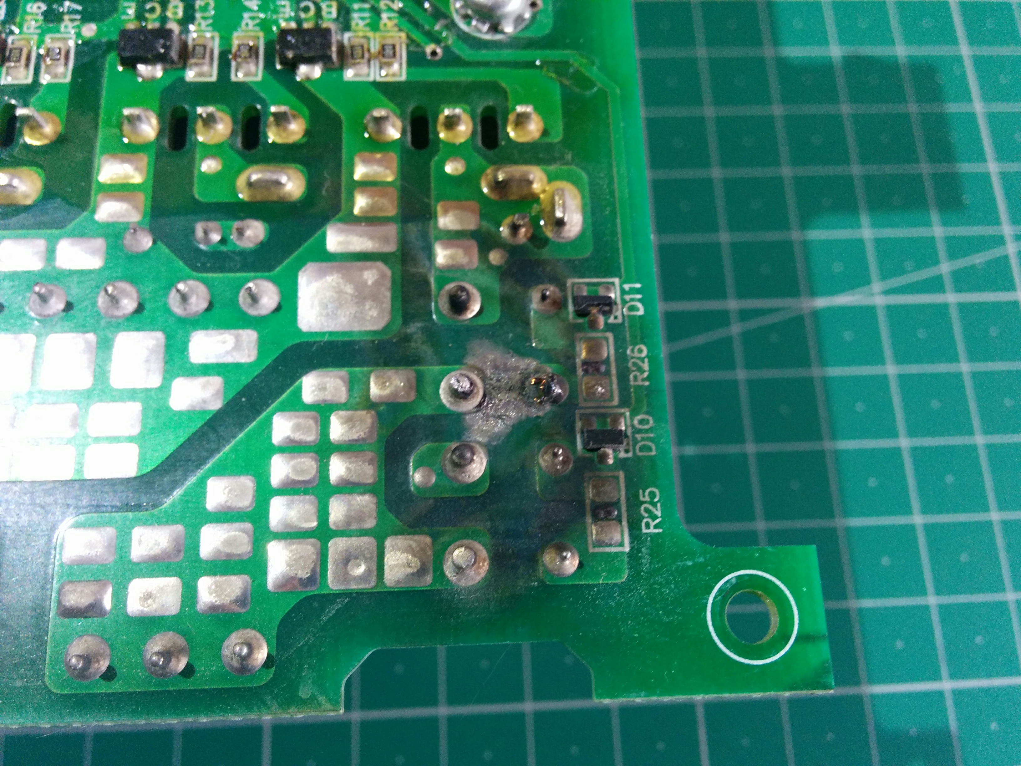
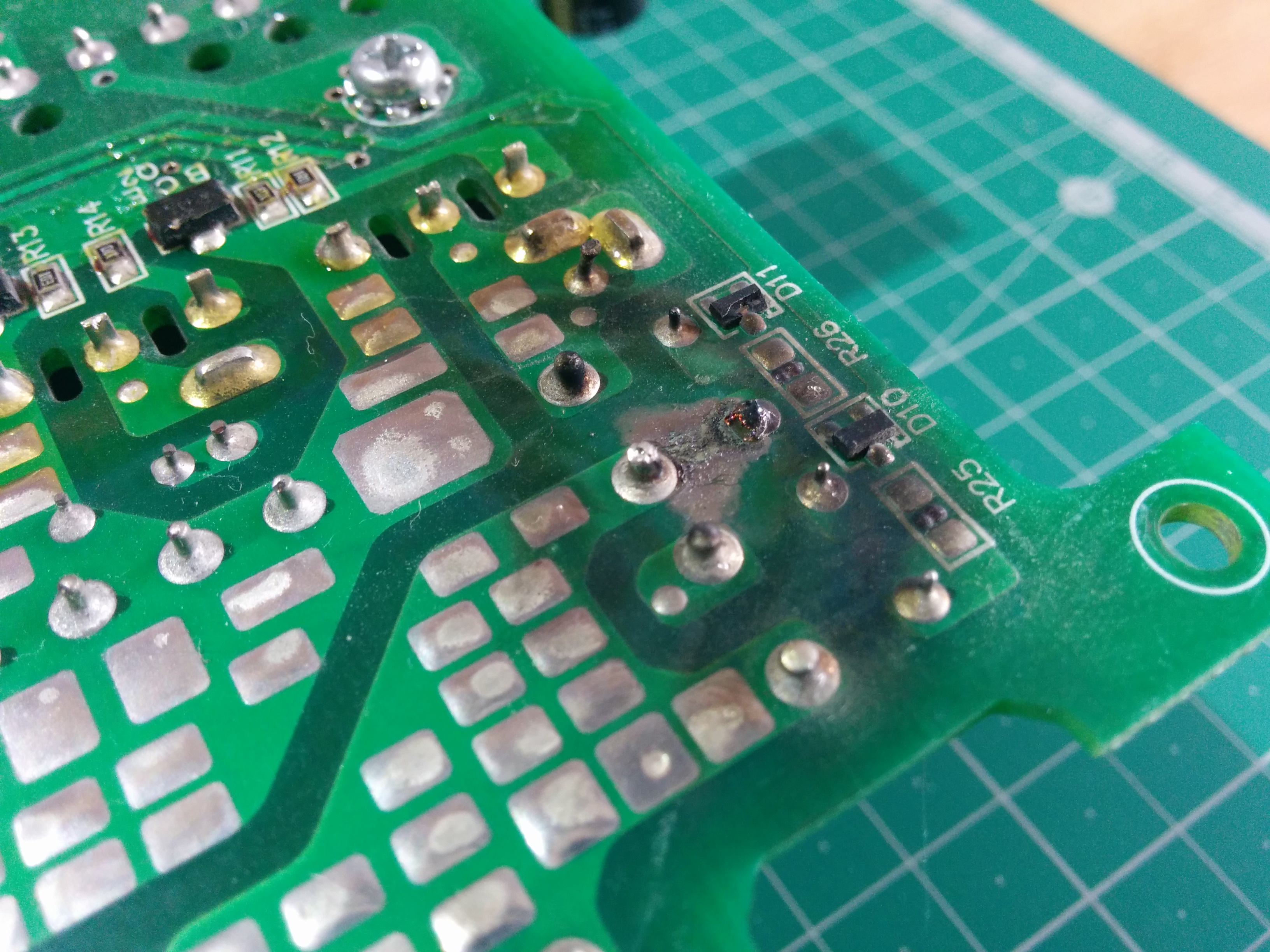
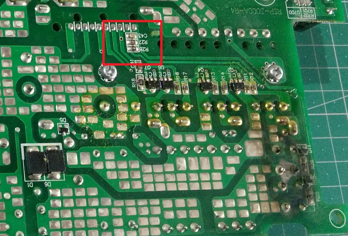
What do we have here? that looks like something went wrong here.
I have no idea what could have happen here, but it does look like it was arcing over. And is make no sense, why would it. I'll get back to this and explain. Desoldered the first power stage. Its part of PFC, which have three mosfets and one diode. Behind it, there is PFC control daughter board, on the right is blue main cap (after PFC stage) 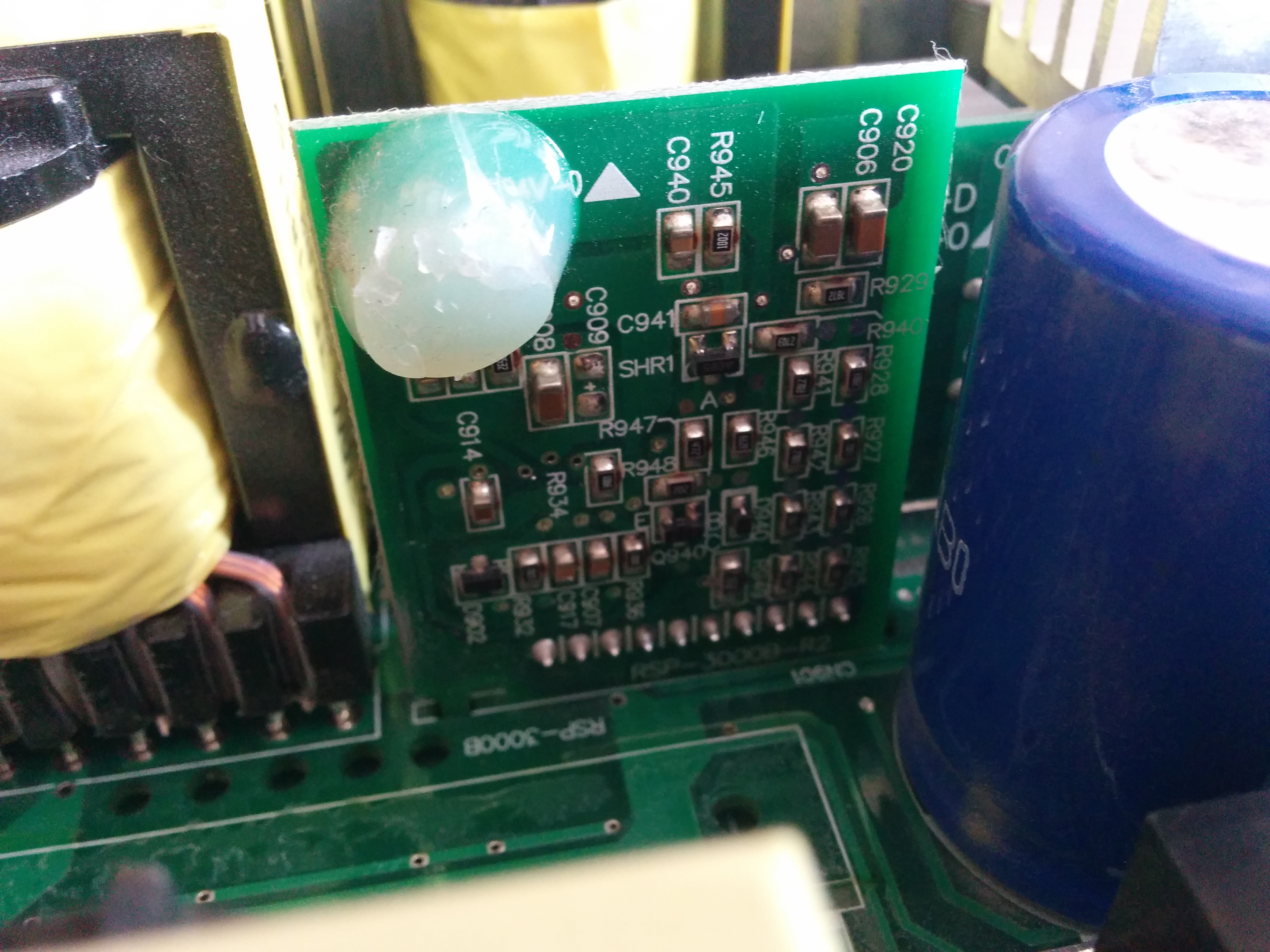
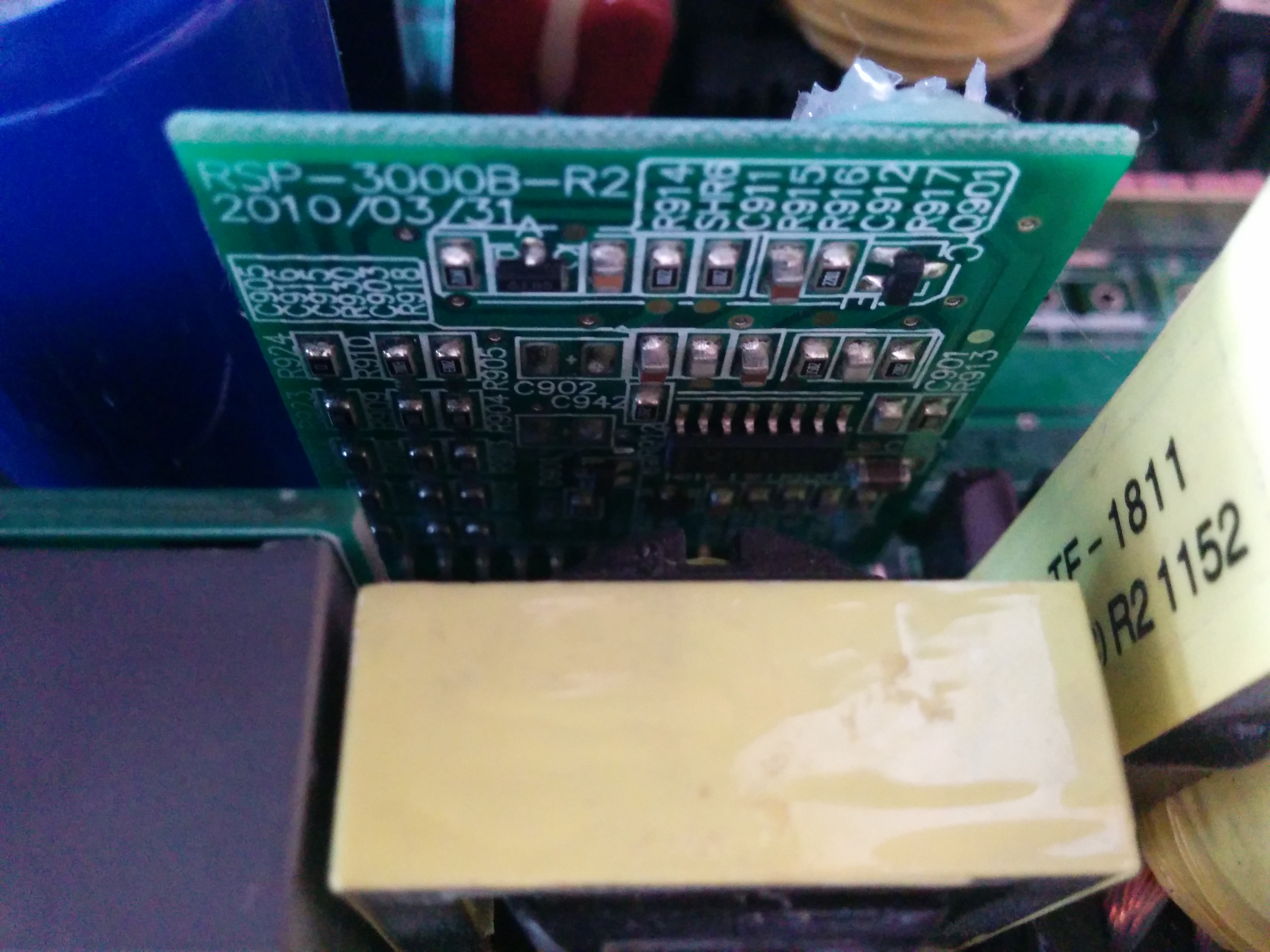
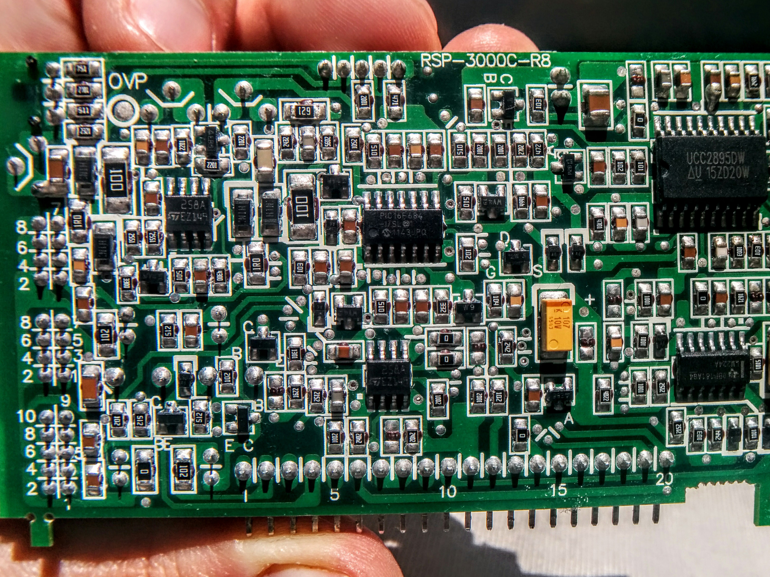
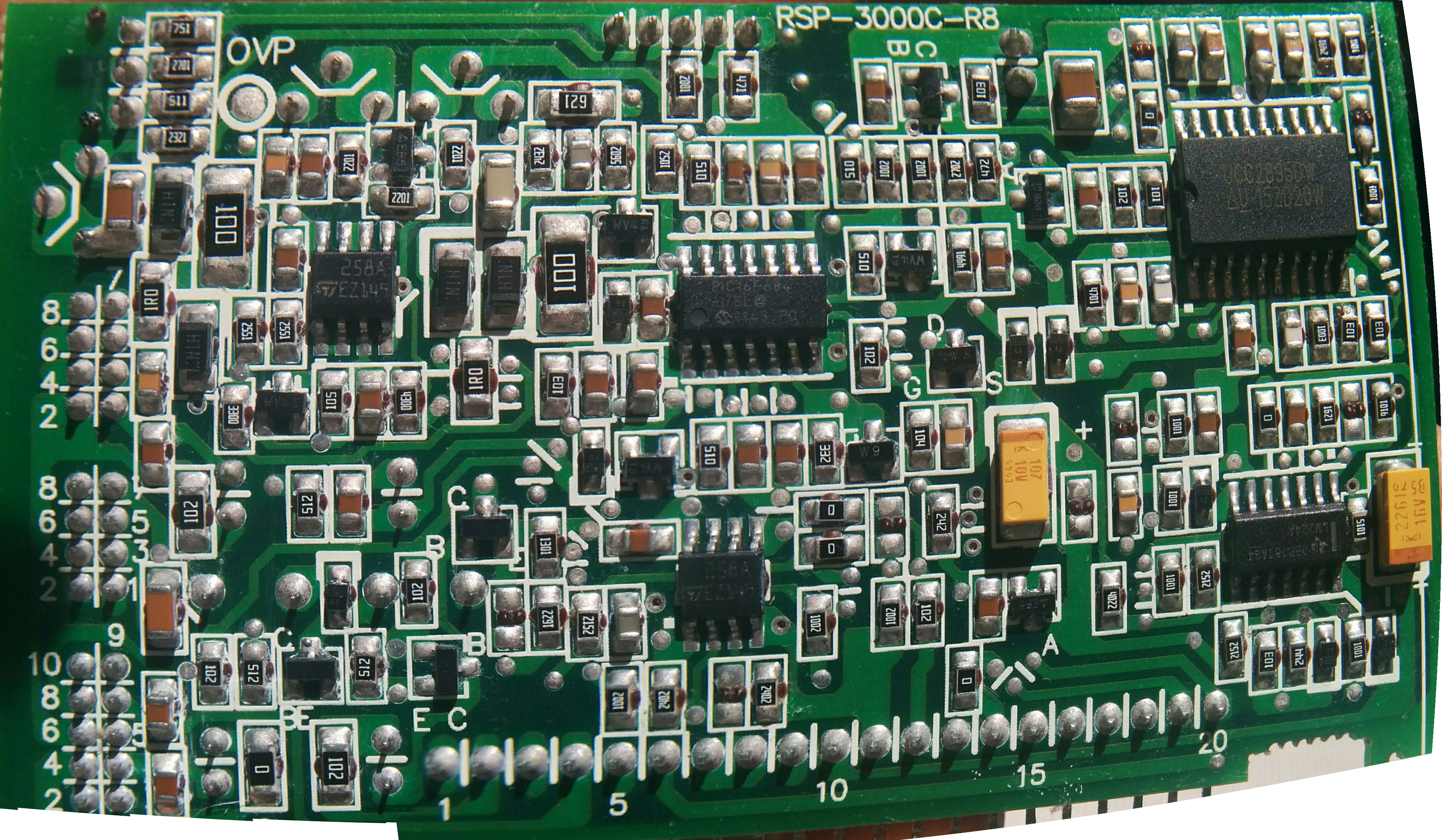
The other side of same PFC control daughter board, which you can't see much since everything is so compact.
Note, that on this board, there is date printed, which would make this supply max of 7 years old. Second thing is that every where you can seen RSP-3000 markings, which is interesting by itself, since there is 3000w, top of the line, version of it also. Does that mean what internals (maybe not fets and diodes) are rated for 3000w? Who knows? No really, if you do or have RSP-3000, do let me know, I would like to see inside of it! Anyway, lets measure PFC diode, which is STTH3006. Yes, that doesn't look good.. Huston we have a problem.. First mosfet is shorted. And from experience, so will be all other, that are in parallel. And they are, damn.. Looking for new mosfets, I had an option to get some that would be better. Went on farnell.com and checked what 600v mosfets with same or lower RdsOn are available. But I had hard time. Whether they had lower ON resistance and higher input/output capacitance or price of over 10€ a piece, going up to 20€! Also no free samples that would work. Looking at Infineon site, you can see how different series of mosfets are compared to each other. C6 is positioned below E6, P6, CP and newer C7. I really like how they have similar series, but some are more easy to use and some are better in performance, but need better layouts and things like that. 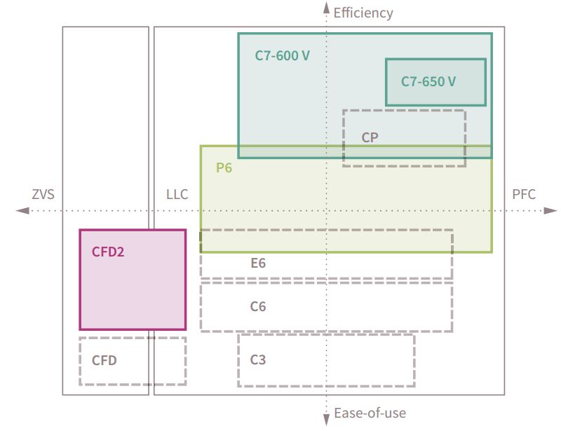
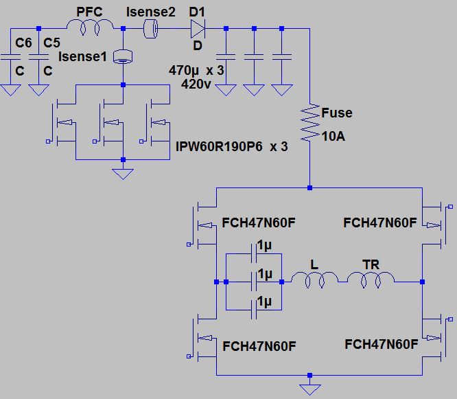
Since I couldn't decide for which one to go for, either E6 or P6 (not for C7, since they don't have them in TO247 yet). I have found, that they have simulation models, which would help a lot. Here is article, where I show you how you can do that with LTspice. In short, I looked at E6 and P6 as well as C7 (even if I can't use them), how they compare to C6, which were in there originally. Until I got them, I still wanted to do some work on supply. And by luck I had one 900v mosfet at hand, which would be good enough for testing. Put that one in, check that there were no shorts and from before I know, that I had correct voltages and even ucc2818 output pulses for fets. This would indicate that first stage is working and could be powered up. But not with mains, since you can't be sure, that everything else behind PFC is ok. Hooked up two of my HP supplys up in series, on first one set both channels to 50v max, on the other to 130v, which is its max. That did power small AUX supply as well as PFC, which charged main caps to almost 390Vdc. So far so good, this is a good start, not totally important stage, since supply (second, output stage) would work without it also, as you will come to find out. And sure enough, it was blown. Measured all 4 fets, which were fine, so I guess fuse saved them, and my pocket, since I didn't have to buy those Mosfets also. Simple desoldering job, added one of my own, 5A ones, for this test time. Connected everything back for testing and... nothing. Supply still in the protect mode. At this point I still didn't had fans connected, I didn't think it would look for them. But I was wrong. After hooking them to board and repowering supply, I saw green light and output voltage! Success! Took some time, left it powered on and keeping my eye on it, making sure all is right. So I needed a load, that would take >2500w, had low ohm value, that would take about 100A of current. The only one thing I could think of, that I could make was, take piece of thin wire (thin for 100A) and use it as resistor, under water, to take away that huge amount of power without burning and melting. Yes, this supply has no problem melting wire, fun fact hehe. And here my next problem laid. Do you know, if you every played with transformer cores or many turns of air inductor, then you pass current through, how the coil jumps, pulls tight, one turn to other, of one part of core to other? Yes, you guessed it, that happened. But since this was bare wire (steel, I think), it shorted turns, lowered resistance and make pretty good short. Supply protected itself, so this part works. I needed to wire not to move with high current, so I wound it on piece of wood, making sure it would stay there. That worked great. This than allowed me to push the supply to its limits. Since this supply has option, to set output voltage with input voltage on of the headers, I did that also, so I had control of output voltage and current. Now the fun part began, pushing supply more and more, until I got to just over 23v, where I had no more control, I couldn't get above that. That could mean only one thing. Something else is damaged, since at 23v and some current, there was only 1700w on output. Ok, when I say "only" I do think that is a lot, but I could't leave it at that. I opened it out, so I had access to some test points on main motherboard. I wanted to look at PFC voltage,I know one of two things must have been at play. Either there was current limit, that was active (and/or was not working right) or I had too little main voltage to supply higher output voltage (if PFC would not work). And since there was already known failure in PFC section, with it's current sense, I was leaning in that direction. Did the same test again and what I saw was, that PFC voltage went down rather soon, with just 100-200w load. That would leave only mains rectified voltage of 320v or below. I think it was more like 300v after the sag of mains @ 1700w. I disassembled it all again. I knew, that current sense transformer had damage around it, one diode that rectifies what voltage did blow and since that was wotking how, I looked at waveform. It was very high, even for unloaded supply, I'm talking 10-20v, far too much. That would make ucc2018 think, that current is already to high and it had to limit it. But why would that voltage be so high? It's like that transformer was not loaded. AHAA! Where are those resistors, since they are not next to diode, where there is pads for them, but were not populated. Following traces I get to this point.
Two 24 resistors in parallel, that seems about right. Measured them and... few kilo ohms, that's right, few kilo's! Almost no load for transformers. Too those out, I replaced them with 22ohms, since that is close enough. Asassembled everything back and get ready for another test. And was it a test! I had on output: 27.45Vdc @ 84.2A, which is just above 2310w. At the same time I had 217Vac @ 12.33A on input with 0.94 power factor, which would read 2540w! Awsome, that still makes this supply 91% efficient. At this point I didn't know if constant current is ok, so I halfed the resistor, so I wouldn't push that much power. Supply did constant current @ 103.7A! What a beast! This supply will draw about 2800w for about 2400w on output. I now call this supply fixed! Parts that had failed: 10A HRC fuse, two 22R smd 0805, one diode in sot23 (BAS16), one and only one PFC mosfet out of three (ipw60r190c6) and.. that is it. One thing that is very interesting is this: output current sense does not use sense resistors! It uses FHS 40-P/SP600 from LEM, check that out.
Main controller board:
RSP2400-24 visits: |
|
Application Note on bridging audio amplifiers
A discussion on bridging audio amplifier circuits like LM3886. Includes a schematic to drive a matched pair of amplifiers in a bridged configuration, power supply considerations for LM3886 and TDA1514 power amplifier circuits-especially in bridged pairs. |
Application Note on parallel-bridging LM3886 audio amplifiers
How to make it loud - real loud. (230 watts rms into 8 ohms without clipping from 4 ICs. How to match LM3886s for parallel operation, then bridge the matched parallel banks. If you are not familiar with bridging amplifiers (BTL configuration), read the Application Note on bridging listed left in article Application Note on bridging audio amplifiers. |
| My first car audio system My second car audio system My third car audio system |