|
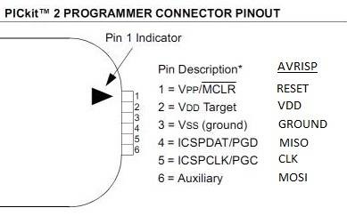
OTA WILL NOT WORK(for now) FOR NODEs THAT ARE GOING TO SLEEP, to save battery There are few steps you need to take, before you can start. This is the hardware and software (I have) you will need: PICKit2 (can be clone) WinAVR (https://sourceforge.net/projects/winavr/files/WinAVR/20100110/WinAVR-20100110-install.exe/download) AVRDUDESS (http://blog.zakkemble.co.uk/avrdudess-a-gui-for-avrdude/), download >>> http://blog.zakkemble.co.uk/download/setup-AVRDUDESS-2.4.exe Try without this step first, I don't have libusb0.dll next to avrdude.exe. If AVRDUDESS works, you can skip this step, since you are doing with this program only (It's been so long, can't remember what is bare minimum) AVRDUDE requires LibUSB (https://sourceforge.net/projects/libusb-win32/files/libusb-win32-releases/1.2.6.0/libusb-win32-bin-1.2.6.0.zip/download?use_mirror=netix) LibUSB should really be installed the normal way as a driver for a LibUSB device, but if you don’t have any such devices then you will need to download this. Extract libusb-win32-bin-1.2.6.0/bin/x86/libusb_x86.dll to where you have avrdude.exe placed and rename libusb_x86.dll to libusb0.dll You connect PICKIT2 to 5v arduino (maybe this works if you have level shifters for 3.3v version), which means you MUST NOT HAVE any external flash and RFM69 (or similar) connected, since they are 3.6v max devices, and pickit2 signals are probably 5v. SLIKA p2avr Easy table is :
 Open AVRDUDESS: 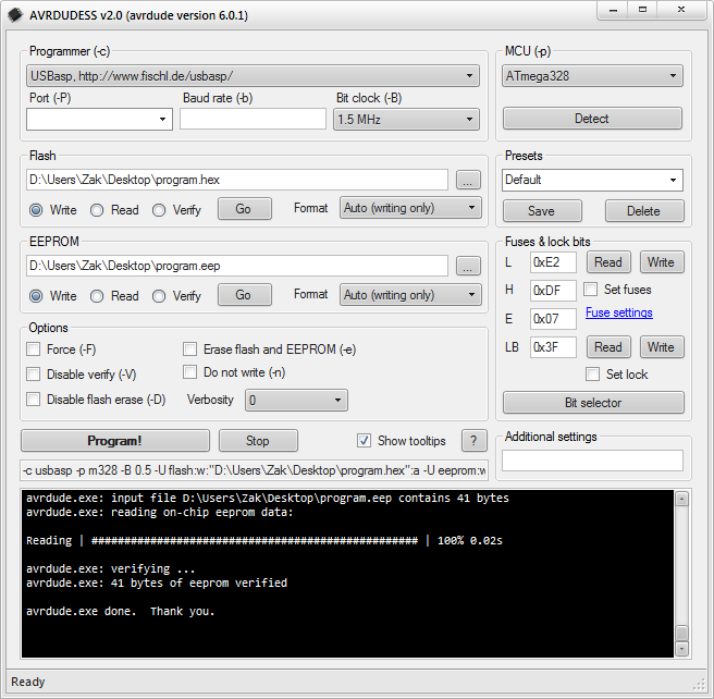 -select programmer = microchip's pickit2 programmer -port = usb Press detect on the right and it should give you atmega328p Read fuses and set them to LO:DE HI:DC EXT:FD and write them, read them and you will see fuses will be changed to new (ext might be 0x05, but that is ok, LO and HI will have to be what you set them at) Under Flash section, you will select your new changed (moteino) bootloader, or moteino bootloader. Make new bootloader or use existing one for moteino: Download it from Felix (https://github.com/LowPowerLab/DualOptiboot) and unpack it somewhere. Apart from files inside, you will also need to copy over boot.h and stk500.h (arduino-1.8.2\hardware\arduino\avr\bootloaders\optiboot\) I did rename the folder to where you now have everything from DualOptiboot-master to DualOptiboot_modded so that I know my bootloader is in there, not original or the one from Felix. Modding bootloader: (this can be skipped if you only want to turn your arduino from ebay to moteino, for that your bootloader is already made(DualOptiboot_V5.0_atmega328_BlinkD9.hex is one of them)) Here is what I did, and what you need to do for your setup is up to you! I had different external flash, which means not only it has different ID, it's commands (from datasheet) were not all the same. My m25p40 has amost everything the same, just one command was a problem. Moteino bootloader has this commands in #define SPIFLASH_STATUSWRITE 0x01 // write status register And for my flash I needed to change to #define SPIFLASH_STATUSWRITE 0x01 // write status register Now you go and make .hex from this. Open windows START and type cmd, right click on it and run as administrator use "cd" to change folder to your DualOptiboot_modded folder, where you have files for this new bootloader type dir to check that you are in right folder type make atmega328 and your .hex will be created in this folder Congrats, you have your new bootloader. In AVRDUDESS, under flash, click browse and locate your new bootloader. Now you are ready to upload. Press program! and wait few seconds, you should get ( ) Open arduino IDE: go to File > preferences and under Additional Boards Manager URLs add this: if you already have something there add , and https://lowpowerlab.github.io/MoteinoCore/package_LowPowerLab_index.json if it is empty,then just https://lowpowerlab.github.io/MoteinoCore/package_LowPowerLab_index.json Since you have now original or modded moteino bootloader, you will have to change your board to moteino under tools > board (search for moteino and select it) You are now at this point as you would have normal arduino pro mini, nano or any other, you can run any code as you did before new bootloader. (REMEMBER!!: if you have now your new moteinos and old arduinos, which look the same from outside, but inside they have different bootloader and if you select wrong board for bootloader that it is inside, you would be able to upload from IDE, you will get error, check that first) Now for the last and best part: Send sketch OTA: open programmer and target from File>Examples>RFM69>WirelessProgramming_OTA Upload programmer to: 1: normal arduino, don't need flash, just RFM69 (always on 3.3v!!!!!!) 2: your new moteino or bought one Upload from PC, only for the first time to your moteino with flash,RFM69 -change in target.ino few things: - #define NODEID 11 (or anything your would like to have this node ID) - SPIFlash flash(FLASH_SS, 0x2020); //EF30 for windbond 4mbit flash (original mote has flash ID with ED30, you find this from flash datasheet, for my it is 2020, yours might be different again) - CheckForWirelessHEX(radio, flash, true); And // Real sketch code here, let's blink the onboard LED Serial.println("Led"); delay(100); Upload from IDE (make sure you know which COM is for programmer and which is for target if you have them plug in at the same time to your PC) in IDE file > preferences, turn on Show verbose output durring: compilation This will show you, where your sketch hex is stored for Moteino Wireless "OTA" programmer, which is located where programmer and target sketches are RFM69\Examples\WirelessProgramming_OTA (https://lowpowerlab.com/2017/05/26/wireless-programming-updates/) Open program 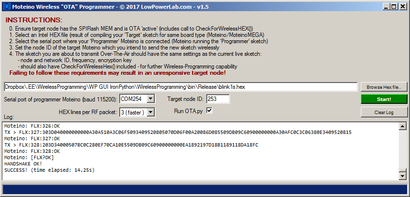 Select COM of your programmer arduino(moteino) enter target node ID (11) which you used when you uploaded target from IDE for the first time Browse for .hex file of your new sketch new sketch will be the same in this case example at was target, just change Serial.println("Led"); to let say Serial.println("New Led"); (Note, if you change ID, #define NODEID 11, to different number and upload OTA, next time that node will have that new number already and 11 won't work from moteino OTA program, you will need to change there too) in IDE don't press UPLOAD, but Verify, button next to it Under sketch you will see some text go past by. After done compiling, scroll up a bit and find something, that will say similar to this: "C:\Users\x\AppData\Local\Arduino15\packages\arduino\tools\avr-gcc\4.9.2-atmel3.5.4-arduino2/bin/avr-objcopy" -O ihex -R .eeprom "C:\Users\x~1\AppData\Local\Temp\arduino_build_128898/Target.ino.elf" "C:\Users\x~1\AppData\Local\Temp\arduino_build_128898/Target.ino.hex" Bingo, AppData\Local\Temp\arduino_build_128898/Target.ino.hex is your .hex to upload. So select this hex file in moteino OTA program and click green button Start! you should get a lot of text Available serial ports found: COM1, COM5, COM11 Moteino: [FLX?OK]
Stock arduino firmware:This file is original arduino bootloader, in name you see what fuses were set, if you ever want to go back to stock arduino bootloaderHow to visits: |
|
Application Note on bridging audio amplifiers
A discussion on bridging audio amplifier circuits like LM3886. Includes a schematic to drive a matched pair of amplifiers in a bridged configuration, power supply considerations for LM3886 and TDA1514 power amplifier circuits-especially in bridged pairs. |
Application Note on parallel-bridging LM3886 audio amplifiers
How to make it loud - real loud. (230 watts rms into 8 ohms without clipping from 4 ICs. How to match LM3886s for parallel operation, then bridge the matched parallel banks. If you are not familiar with bridging amplifiers (BTL configuration), read the Application Note on bridging listed left in article Application Note on bridging audio amplifiers. |
| My first car audio system My second car audio system My third car audio system |