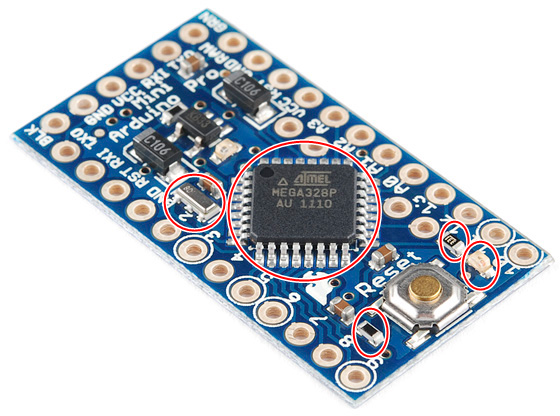
Build guide for MoteinoAs person, that wants to build out of different parts instead of buying complited product, I went the hard way. And since I had bunch of pro mini boards from before to get parts from, this was no brainer for me. Ended up removing 328, led and 3k3 resistor, another 10k resistor and 16MHz resonator.
I had parts for 5 boards, now I needed Moteino boards. R4 looked great to me, price was just under 10$ for 10 boards. All components are 0603, not much different from 0805. I think I even prefer it over 0805 from this project on and you save board space. Capacitors I've put on were 0805 size, had no problem getting them on, pads were big enough. 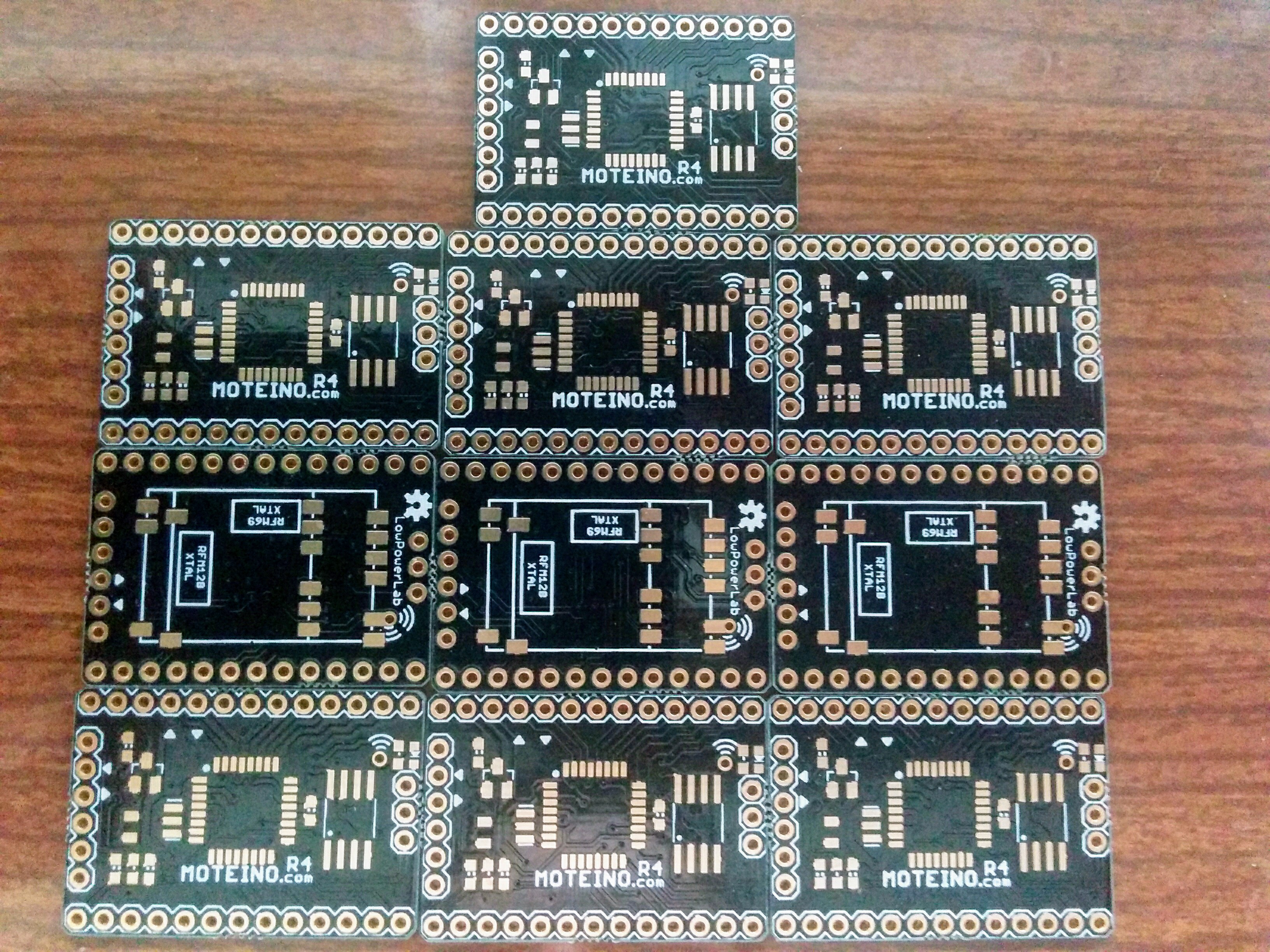
Setting board in vice. 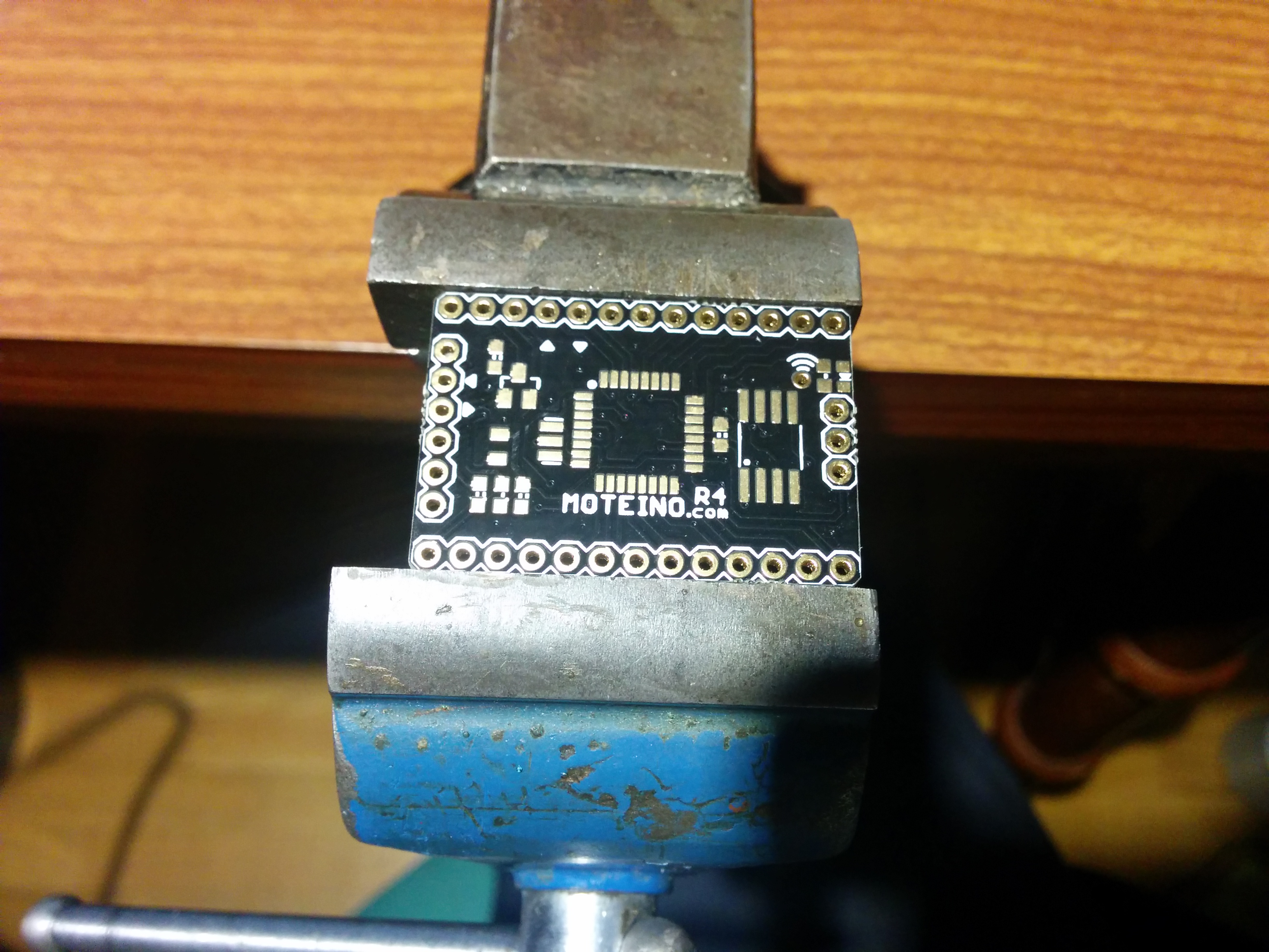
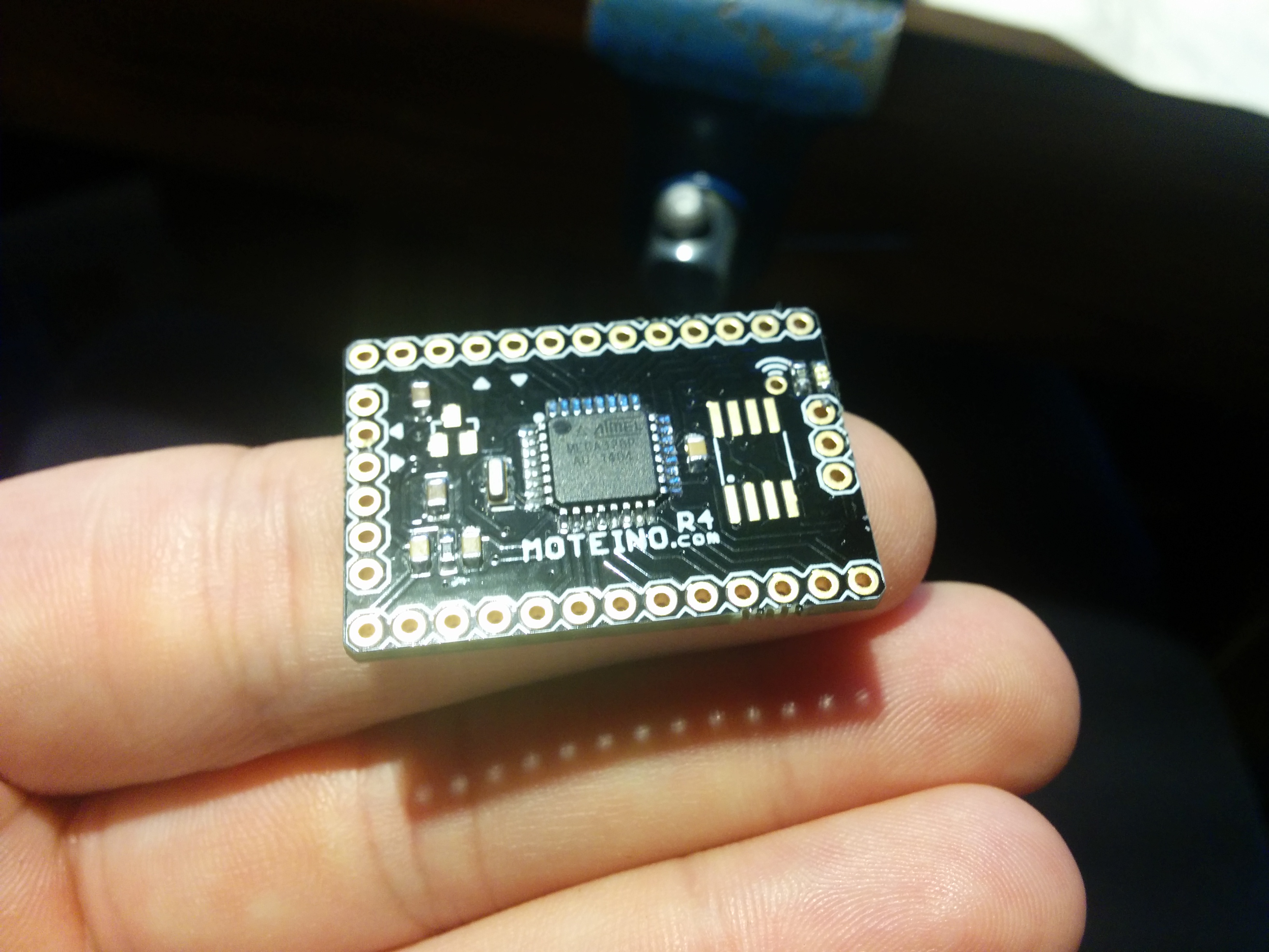
Place solder on one pad of 328. Align and solder that pin and pad. Check your alignment and adjust if needed. Then solder one more pin on other sides, this will lock IC into place while you do one row at a time. 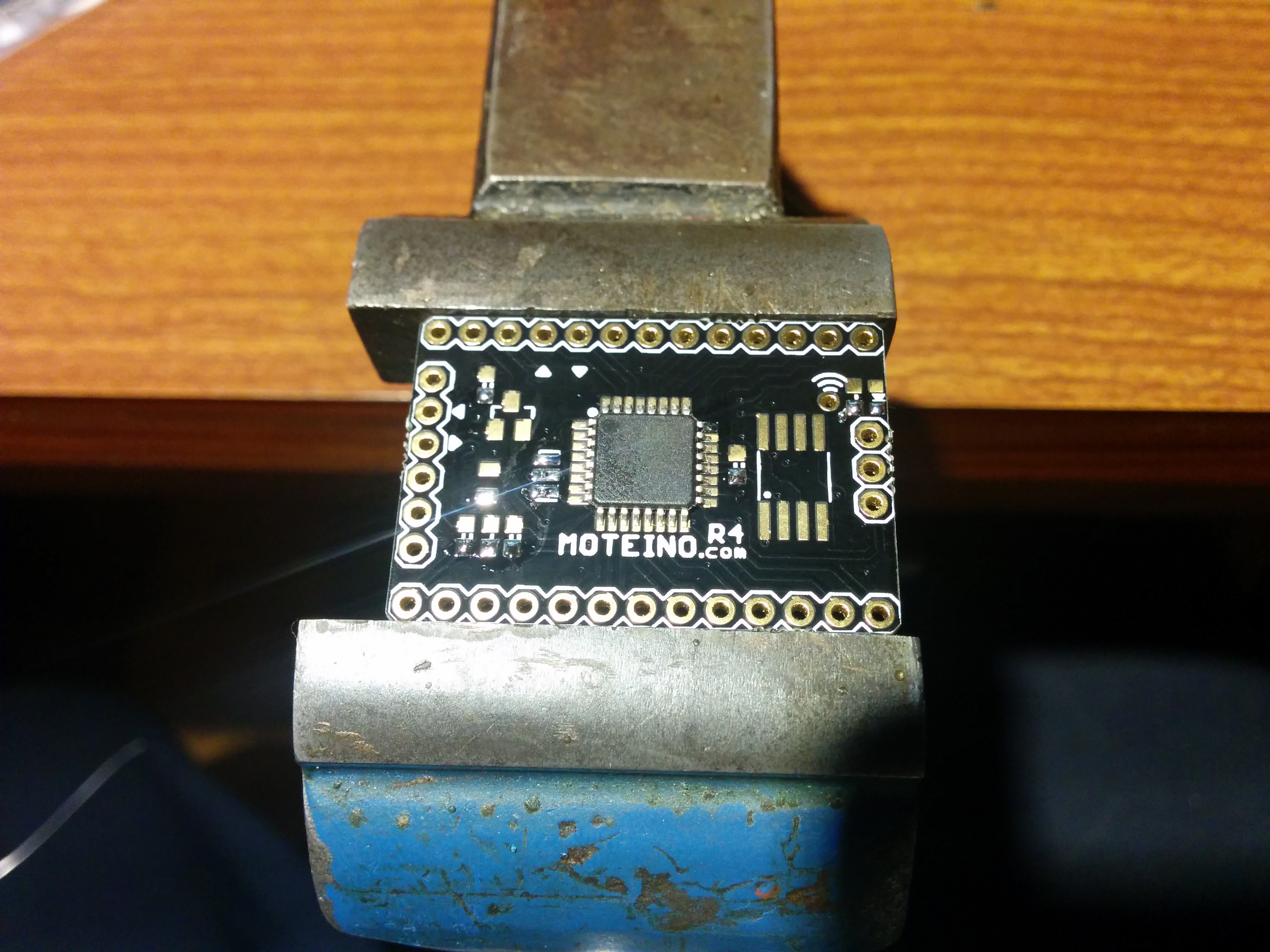
Put flux on all pads/pins. Use a lot of it, it's better than dealing with solder bridges. 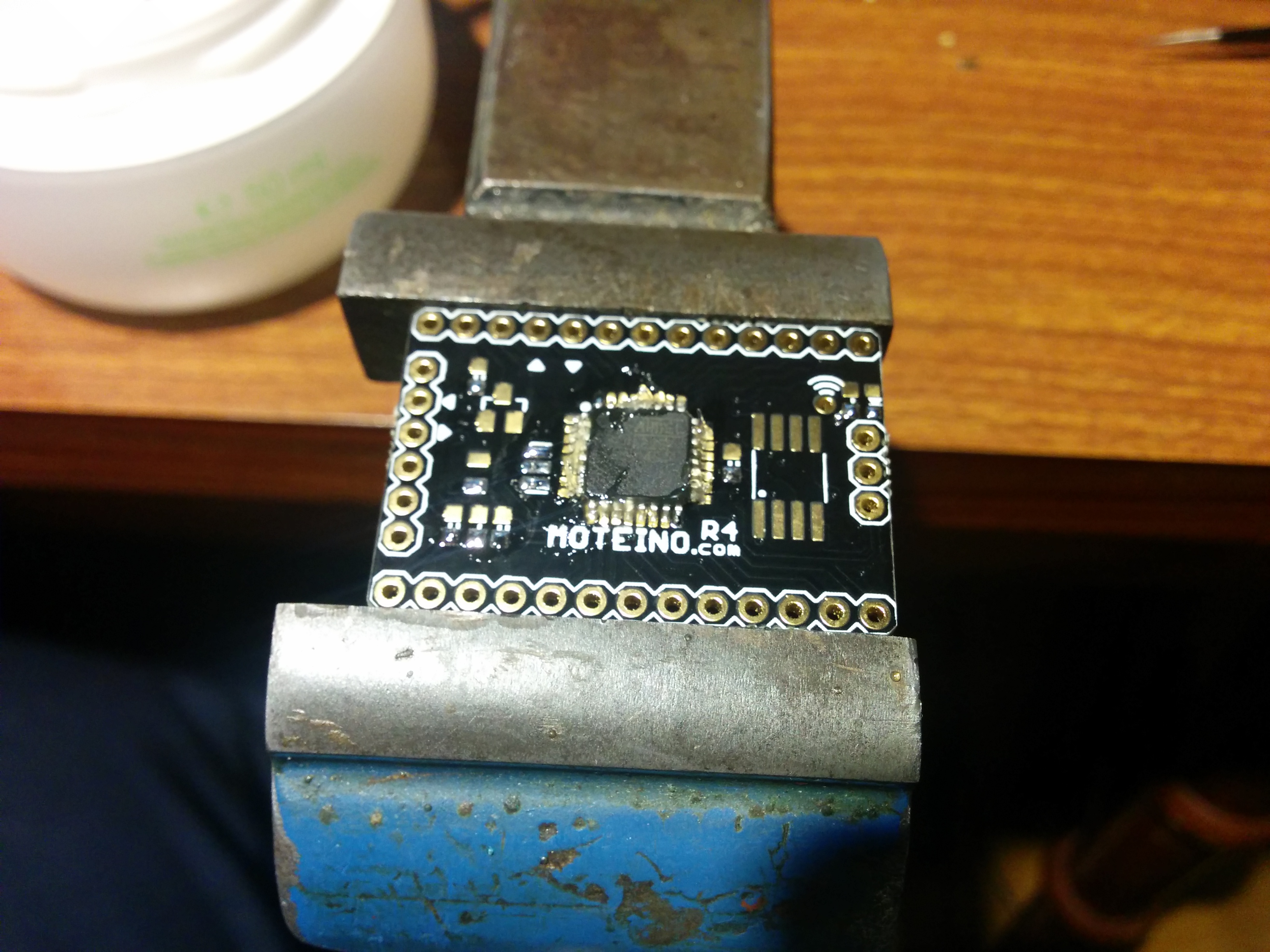
Solder all pins. How to do that, you'll have to figure out by yourself, I will say, youtube is your friend. In the end, you just have to try and try some more to get the filling for it. But i'll say this, less solder, less problems, less in this case is better. I tried draging, taking about 1s per pin, that worked fine for the most part. Double check your work, make sure you don't have any solder bridges! .... Do you see any? 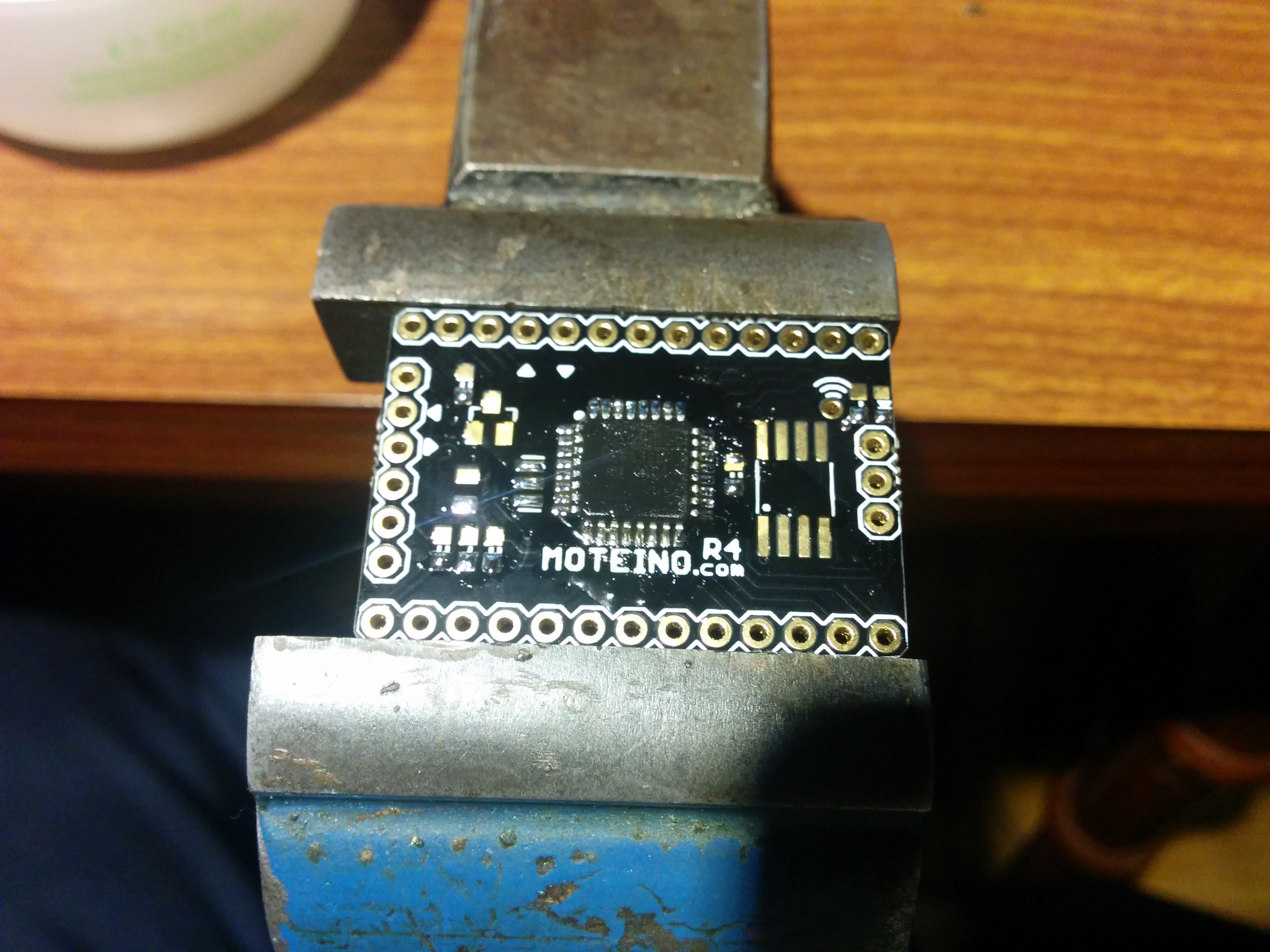
I had trouble also! Took picture with phone, where I was "wait a minute....what's that?" 
All fixed. Also used hot air station to solder resonator. 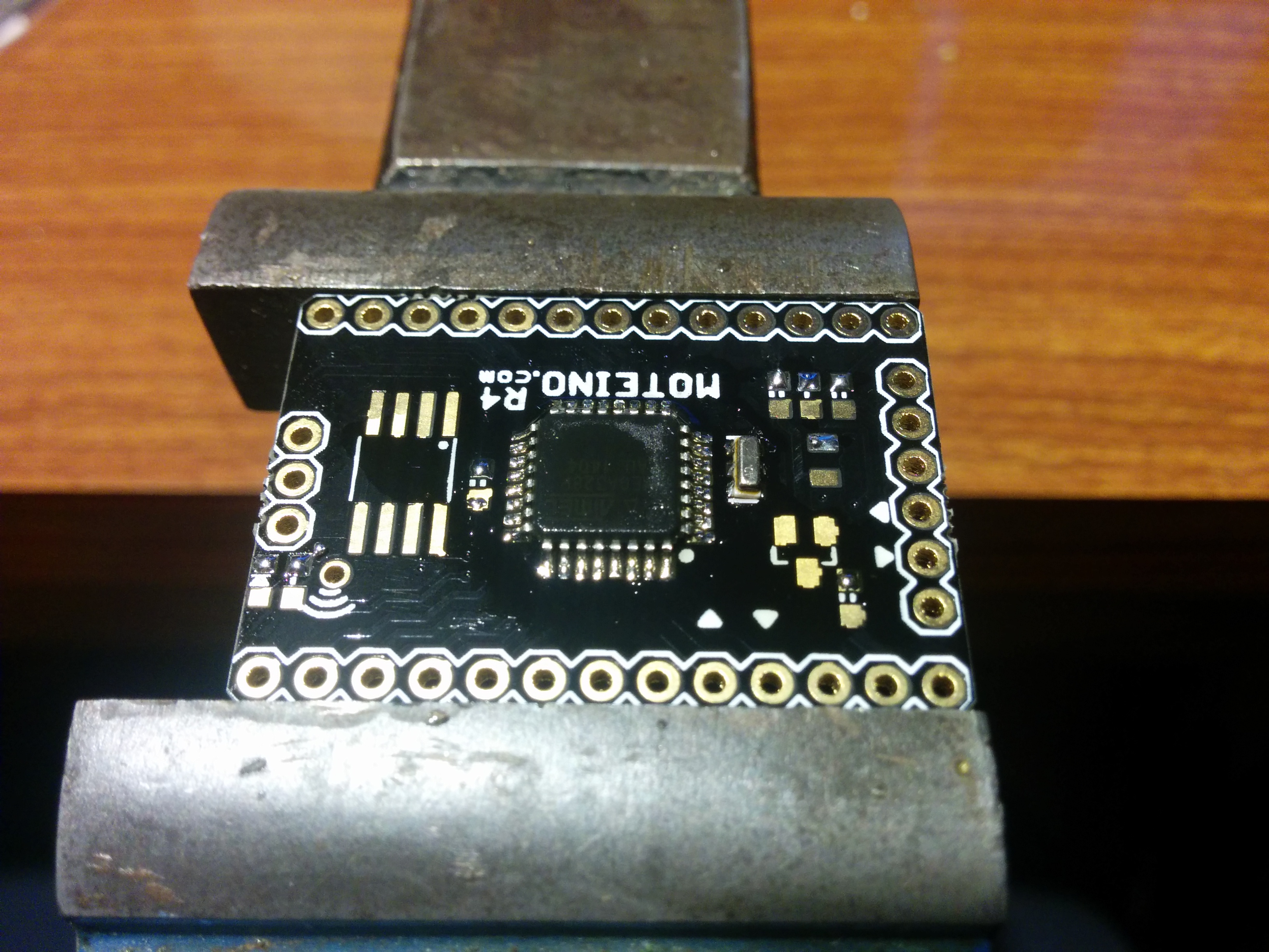
1uF and 100nF caps, 10k resistor... 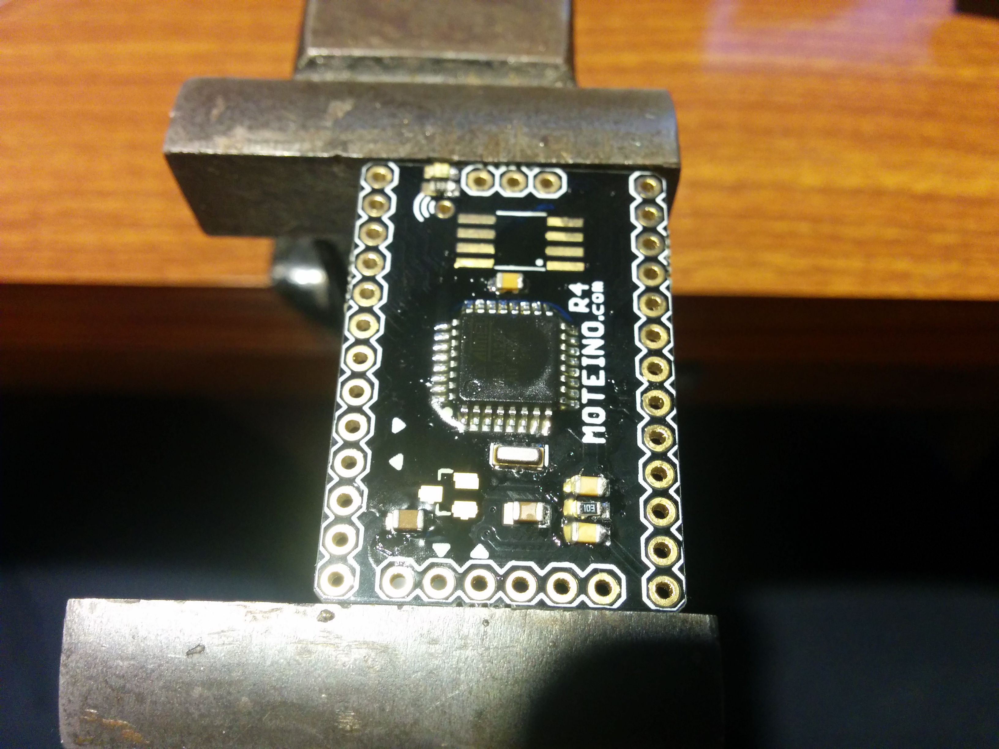
... led and its resistor. 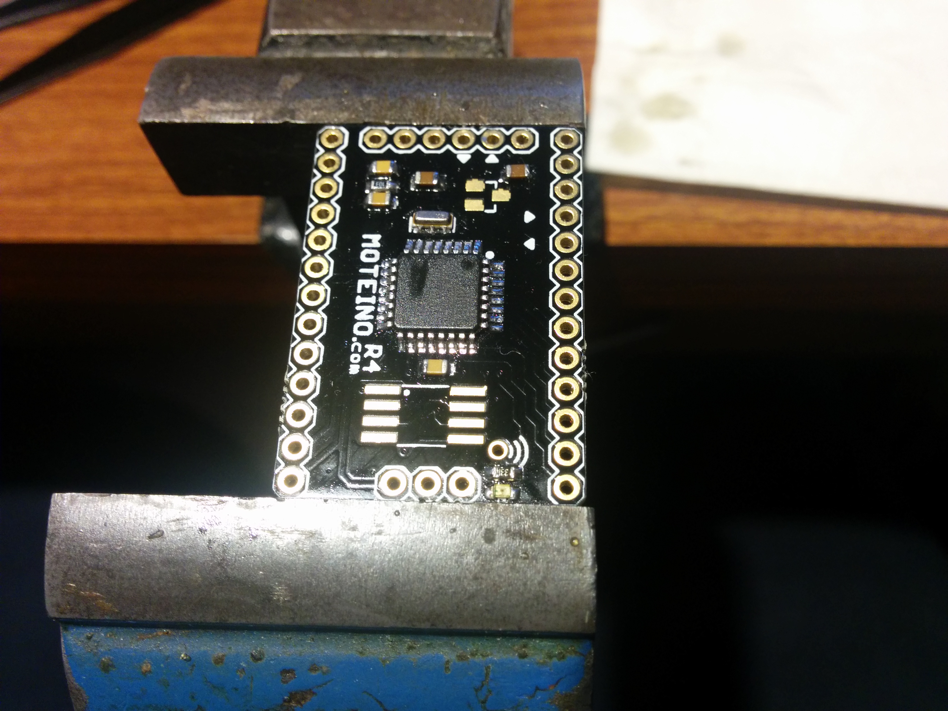
It looks great if I do say so myself. Used Isopropyl alcohol and paper tissue to soak flux into. 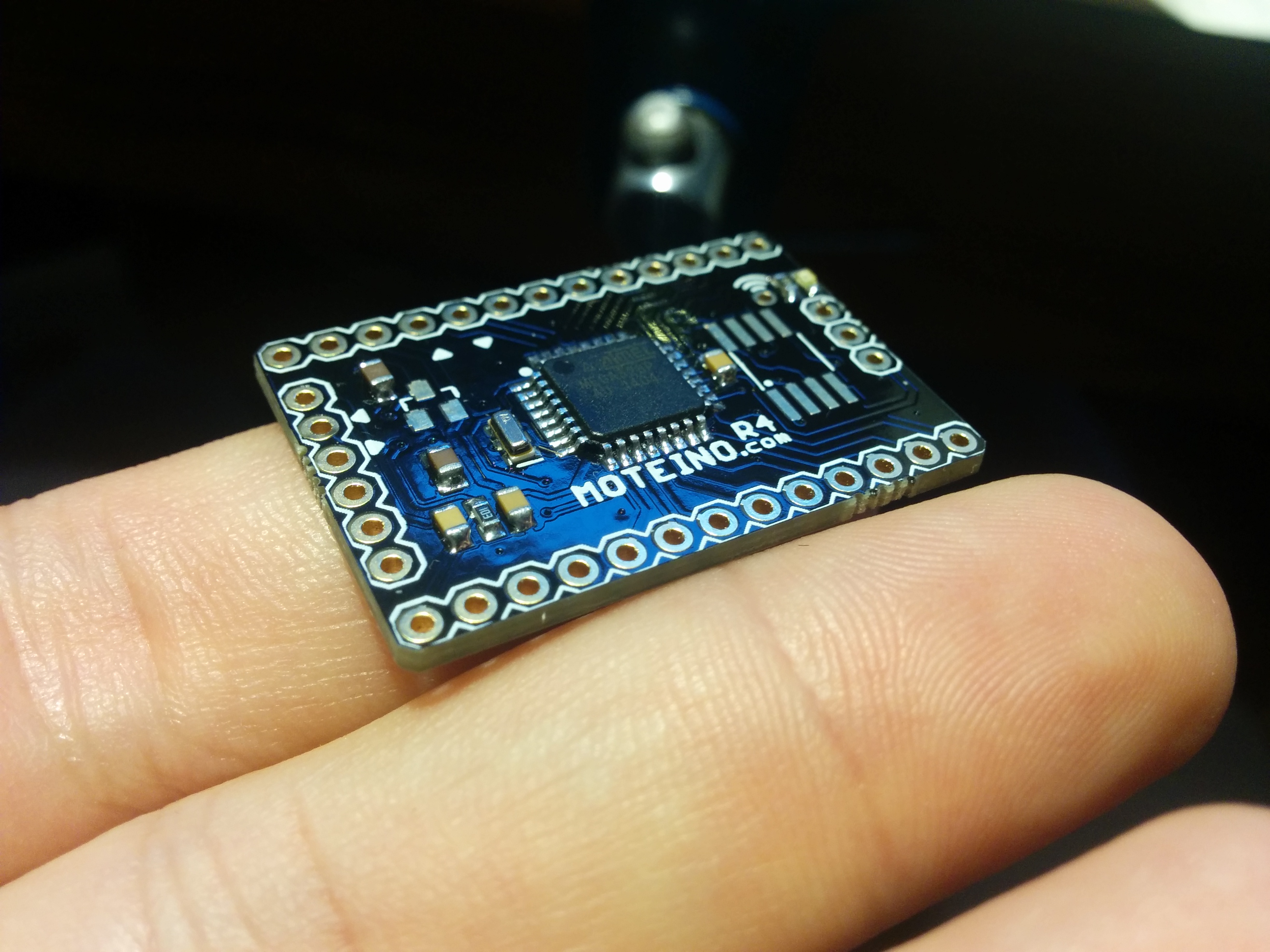
LDO regulator, MCP1703 was also mounted. 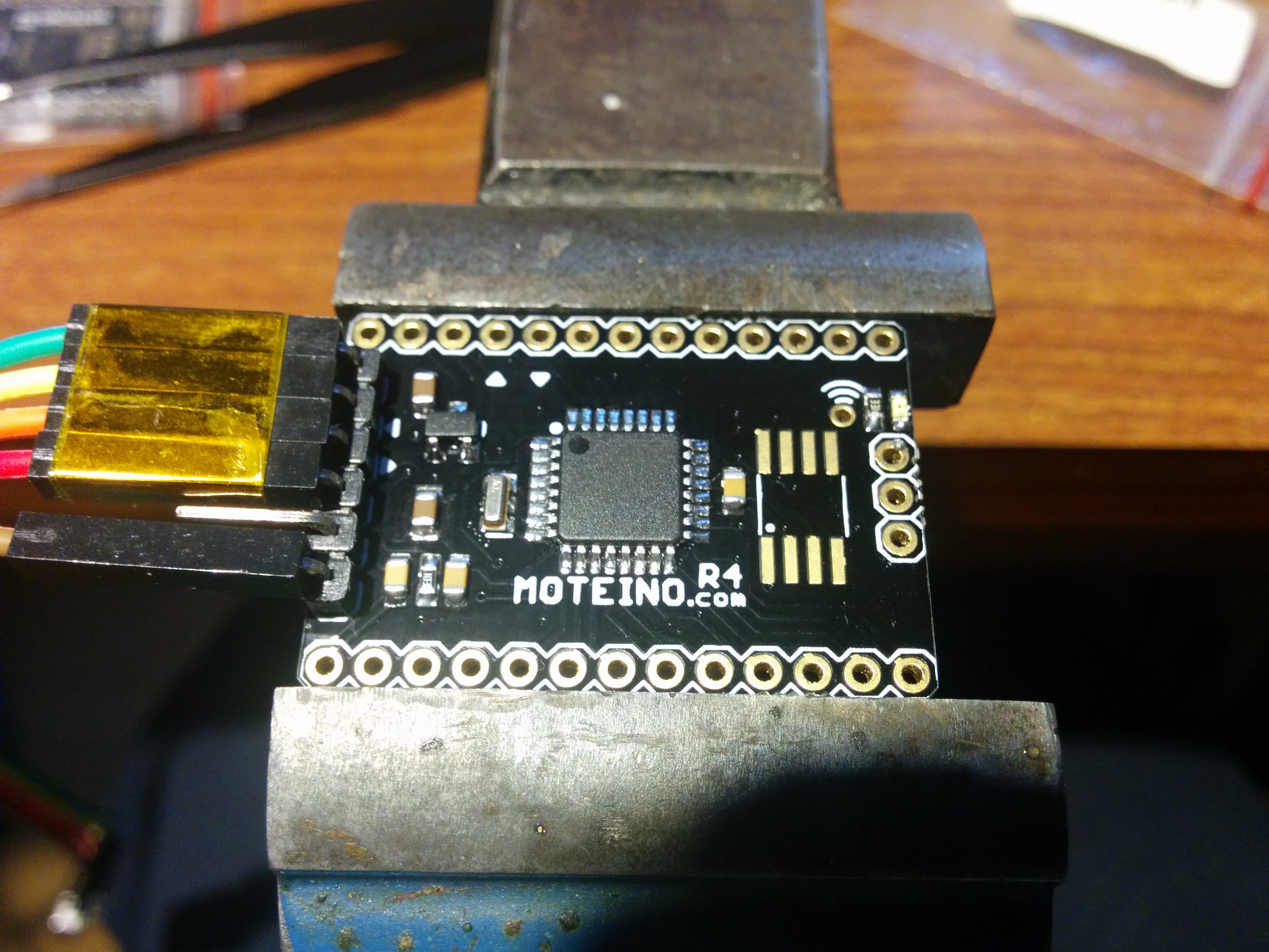
Voltage check on 3.3v. I even think at this point, I only was supplying board with about 3.4v 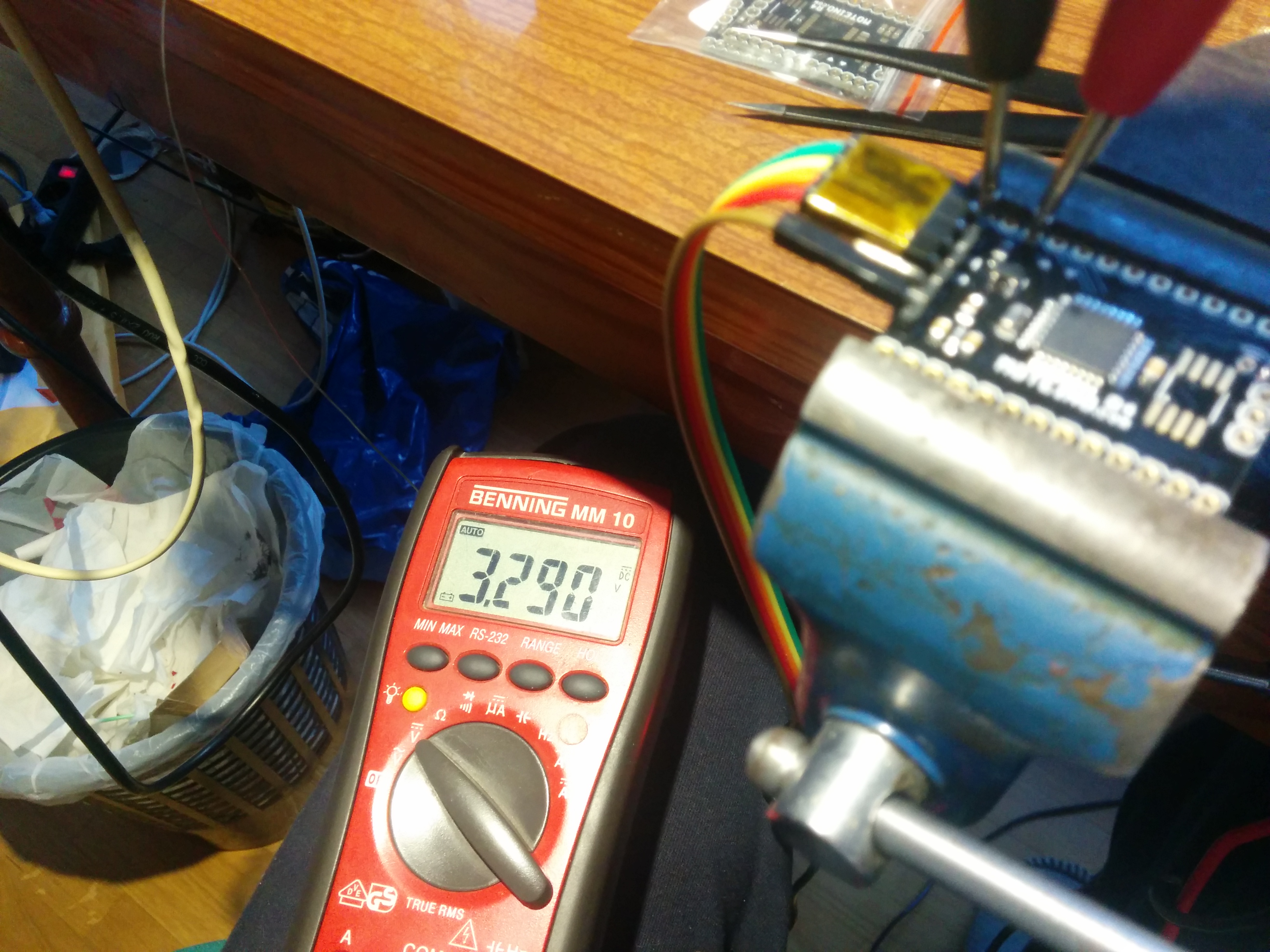
Used potentiometer with two test sketches, to test A7 and A6 and LED as output (pwm). Here with low duty cycle. 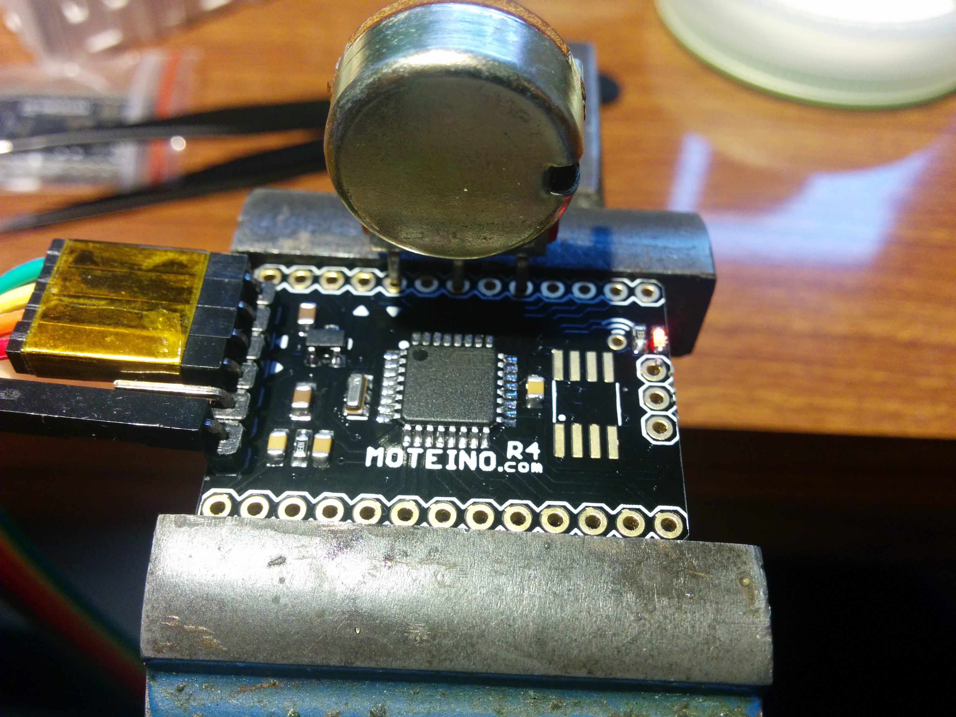
And here with higher one. 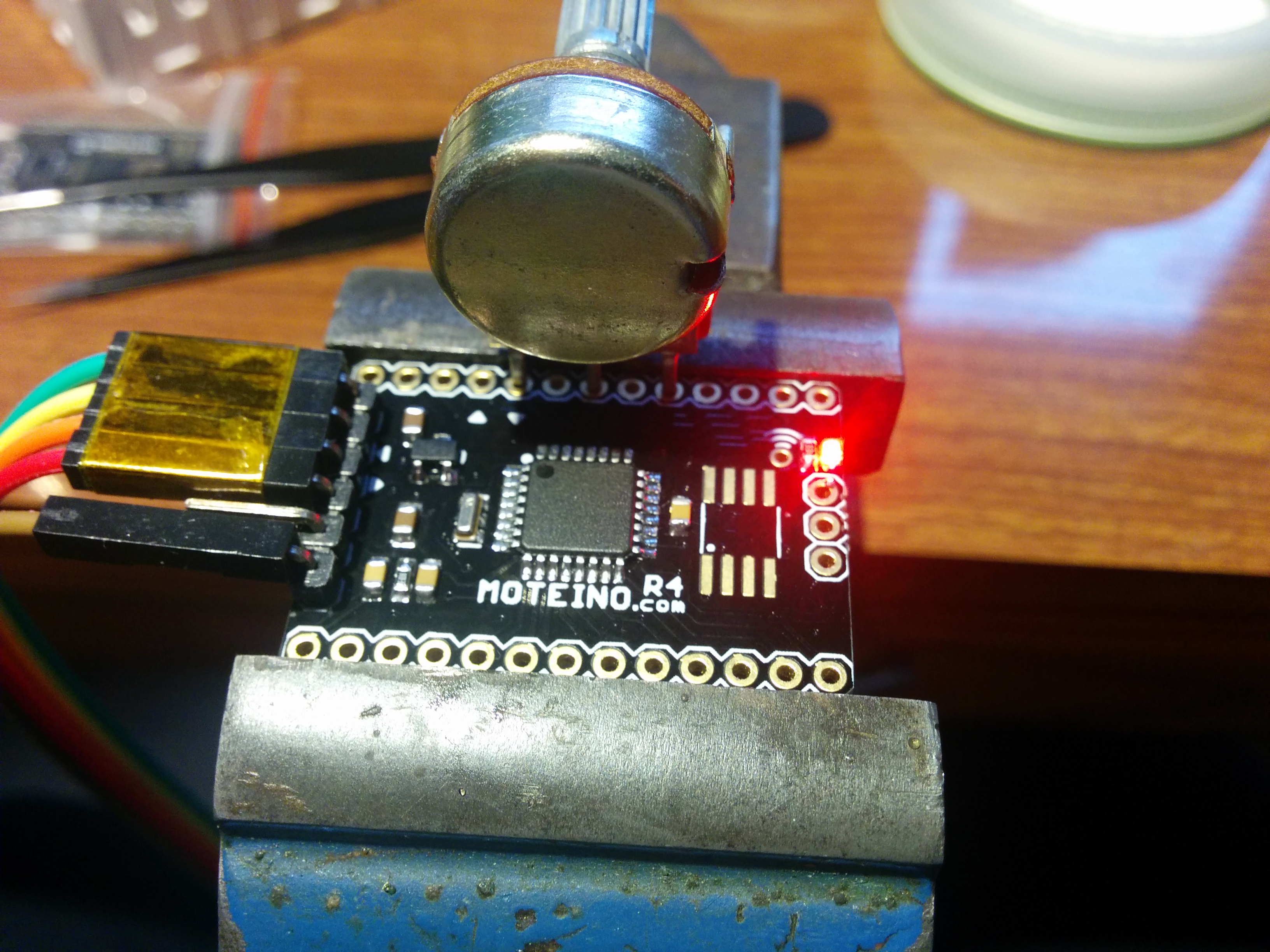
Last thing was to change booatloader for the one Moteino uses. Mine was a bit changed, so I can use it with my flash. One erase instruction was different. 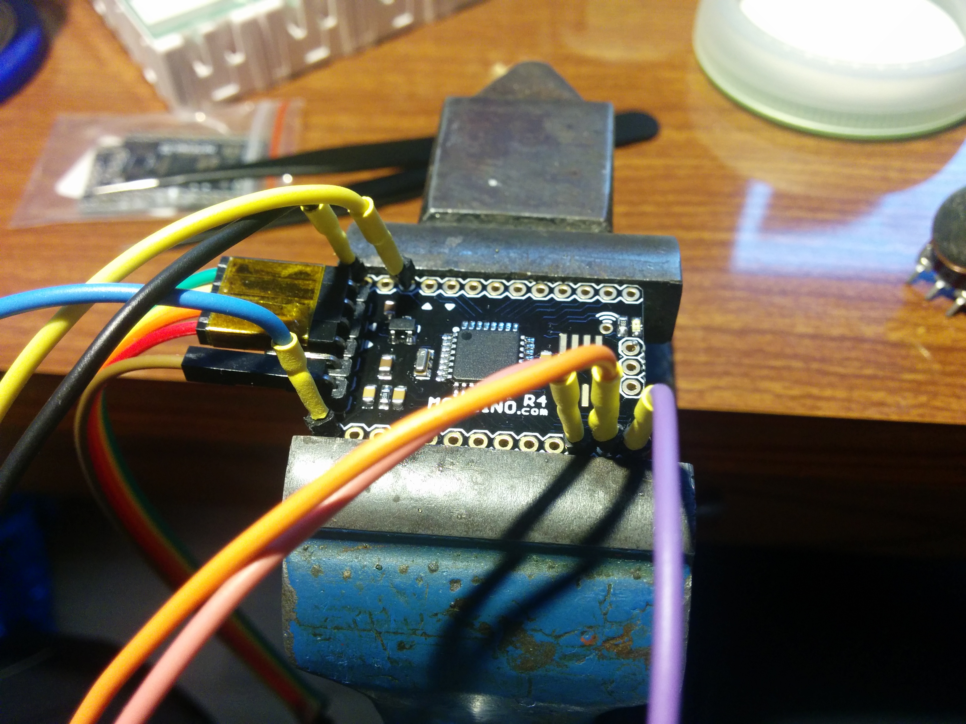
RFM69HW module, for EU 868MHz. 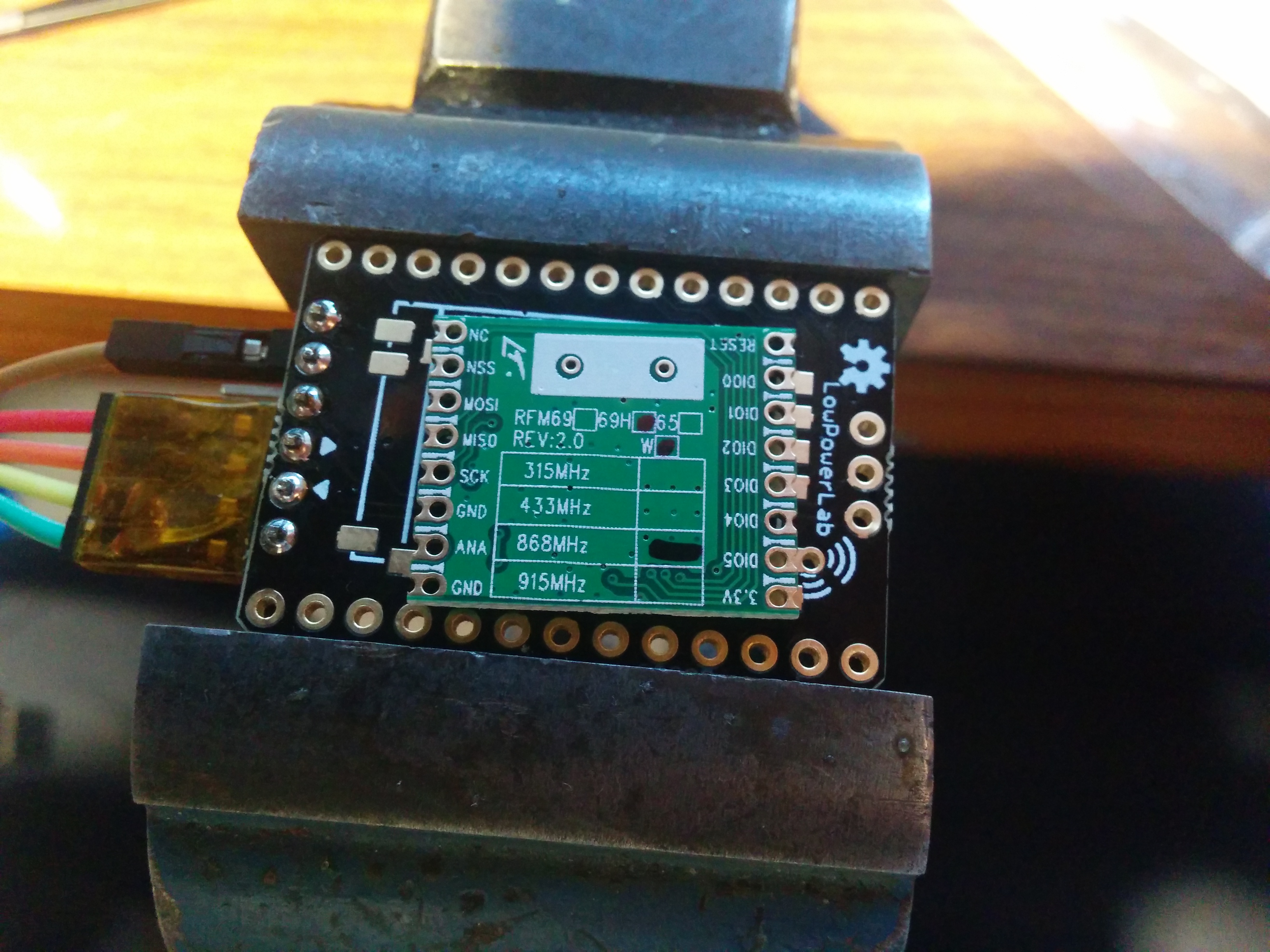
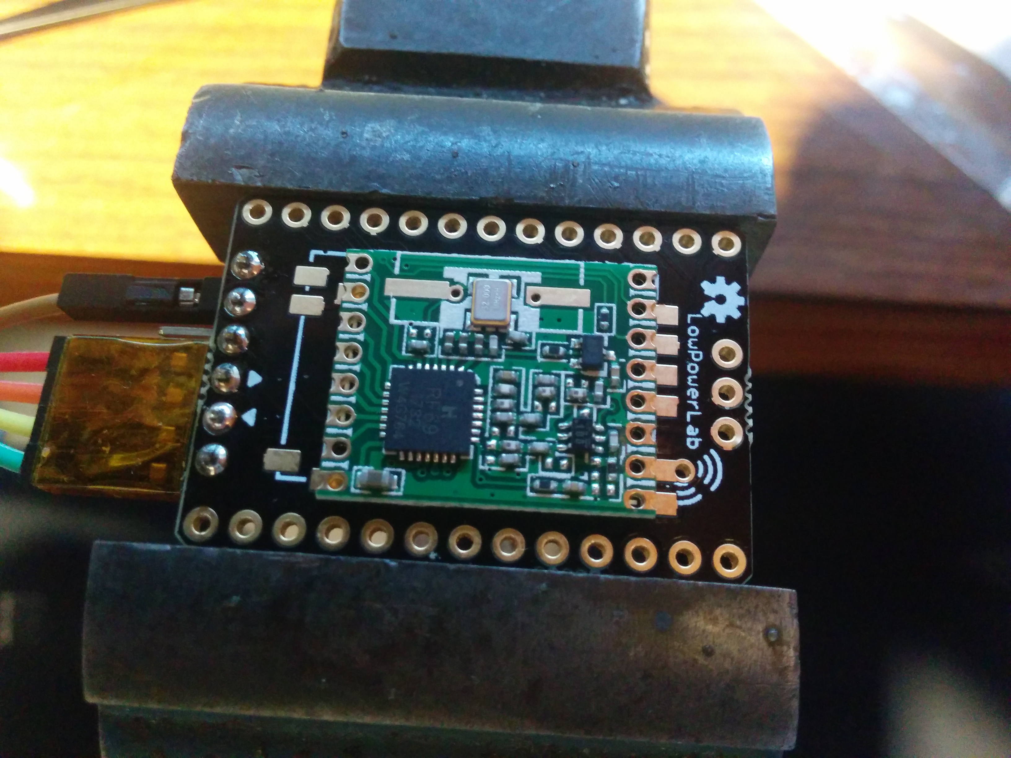
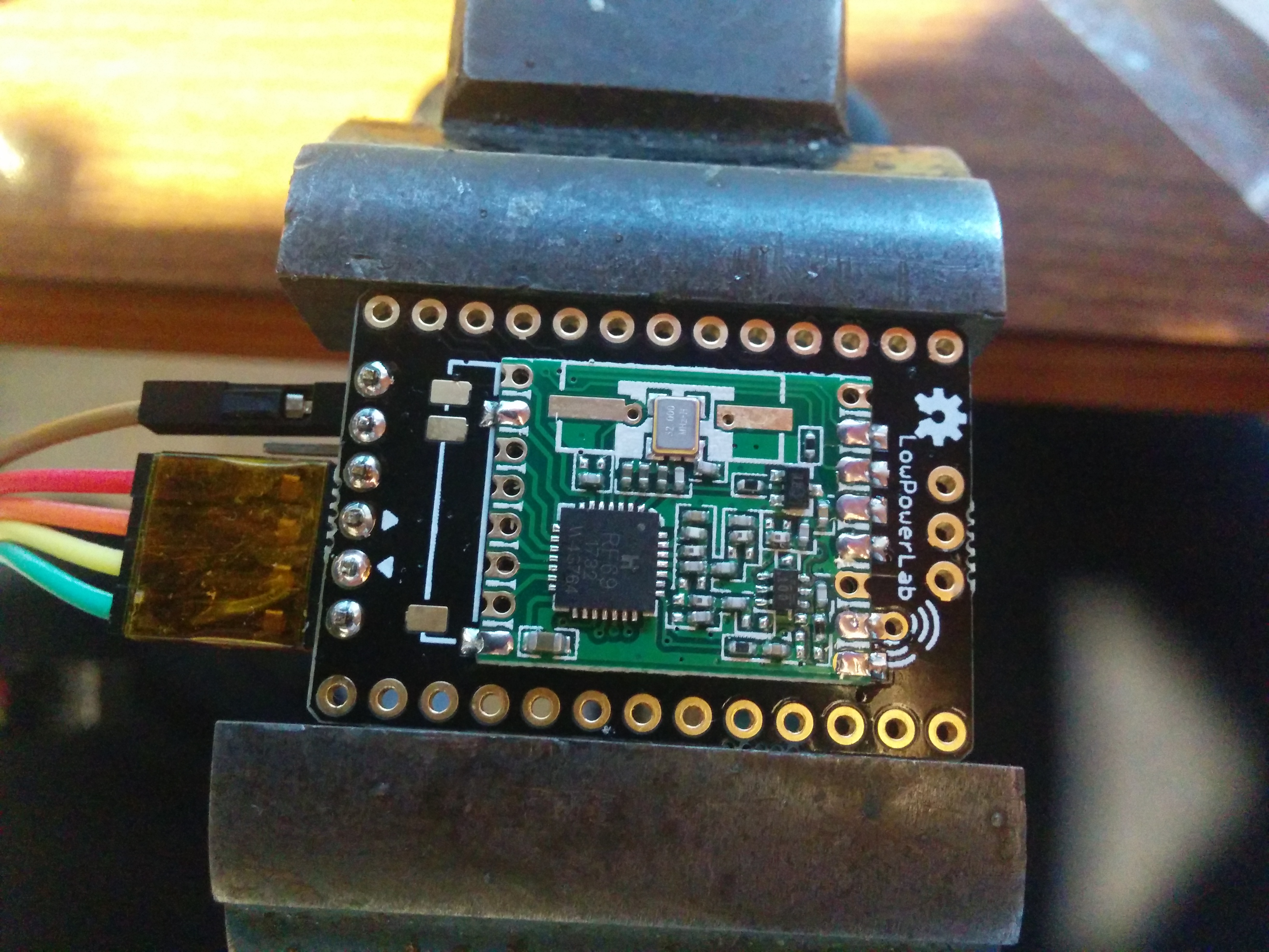
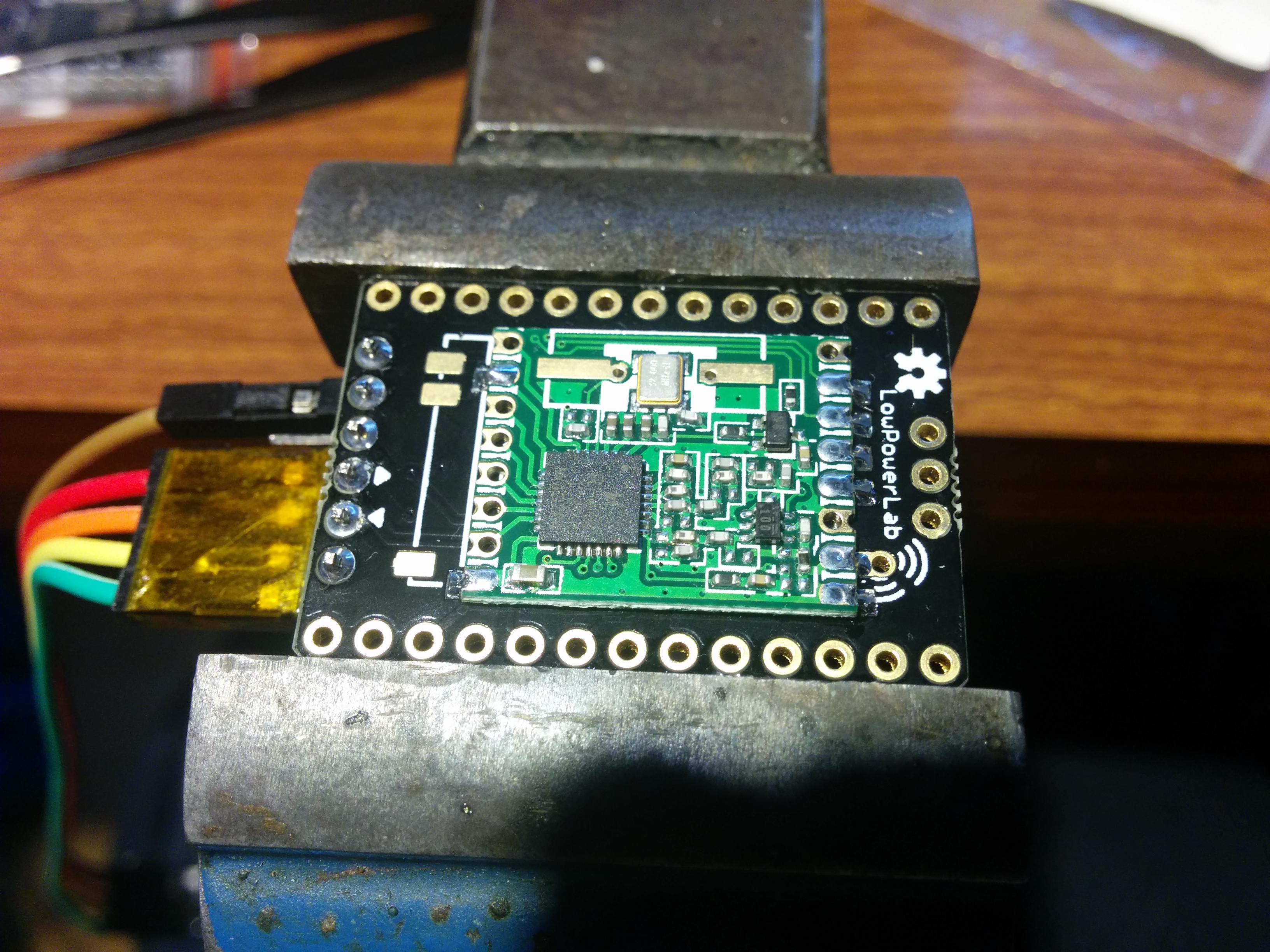
Checked for proper operation. 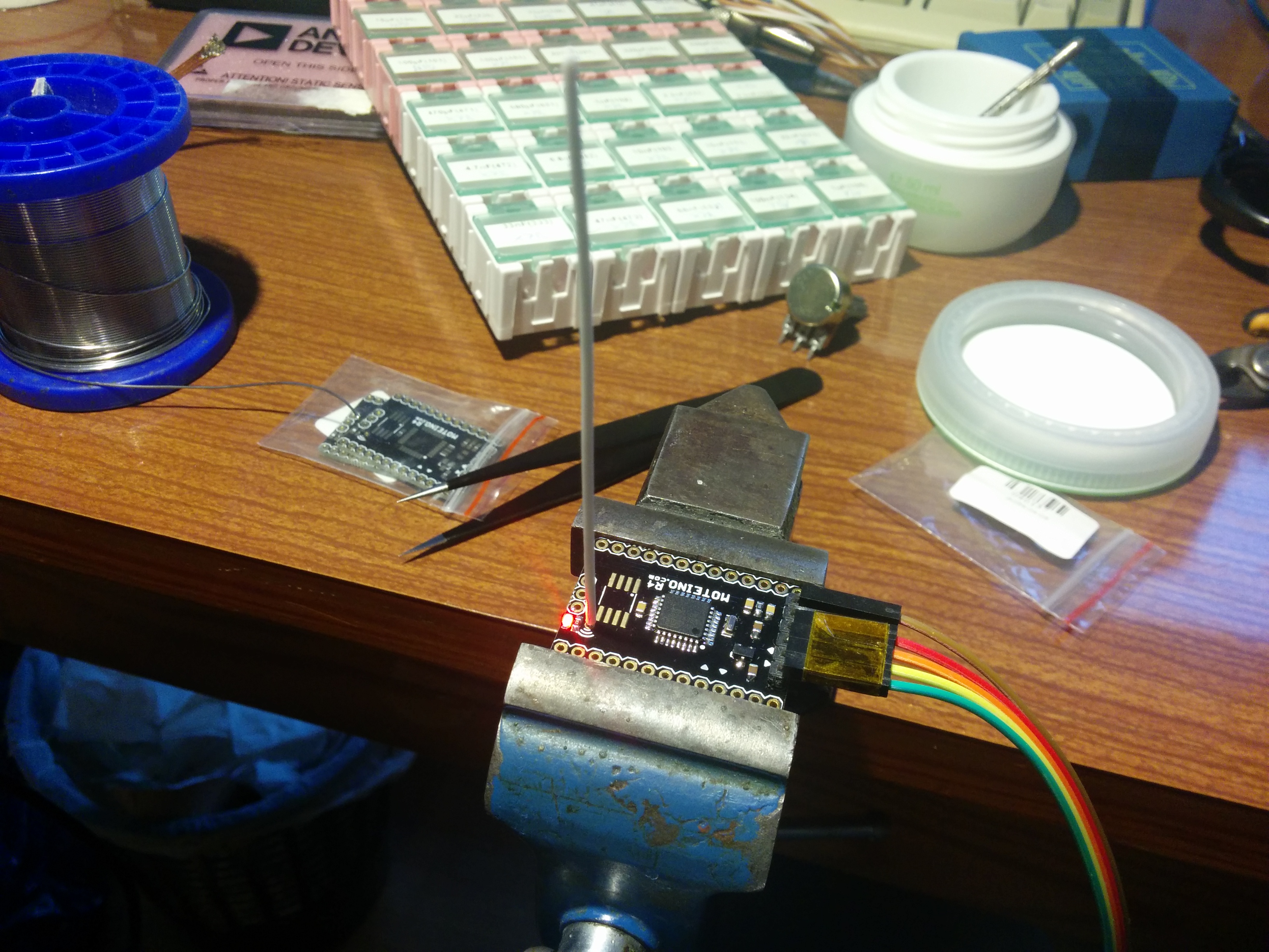
All working and finished. Also no one can't say I didn't try it all, do it all myself. First attempt looked like this. A lot of work, but made it work. Flash and RFM69 connected with wires to Pro mini. 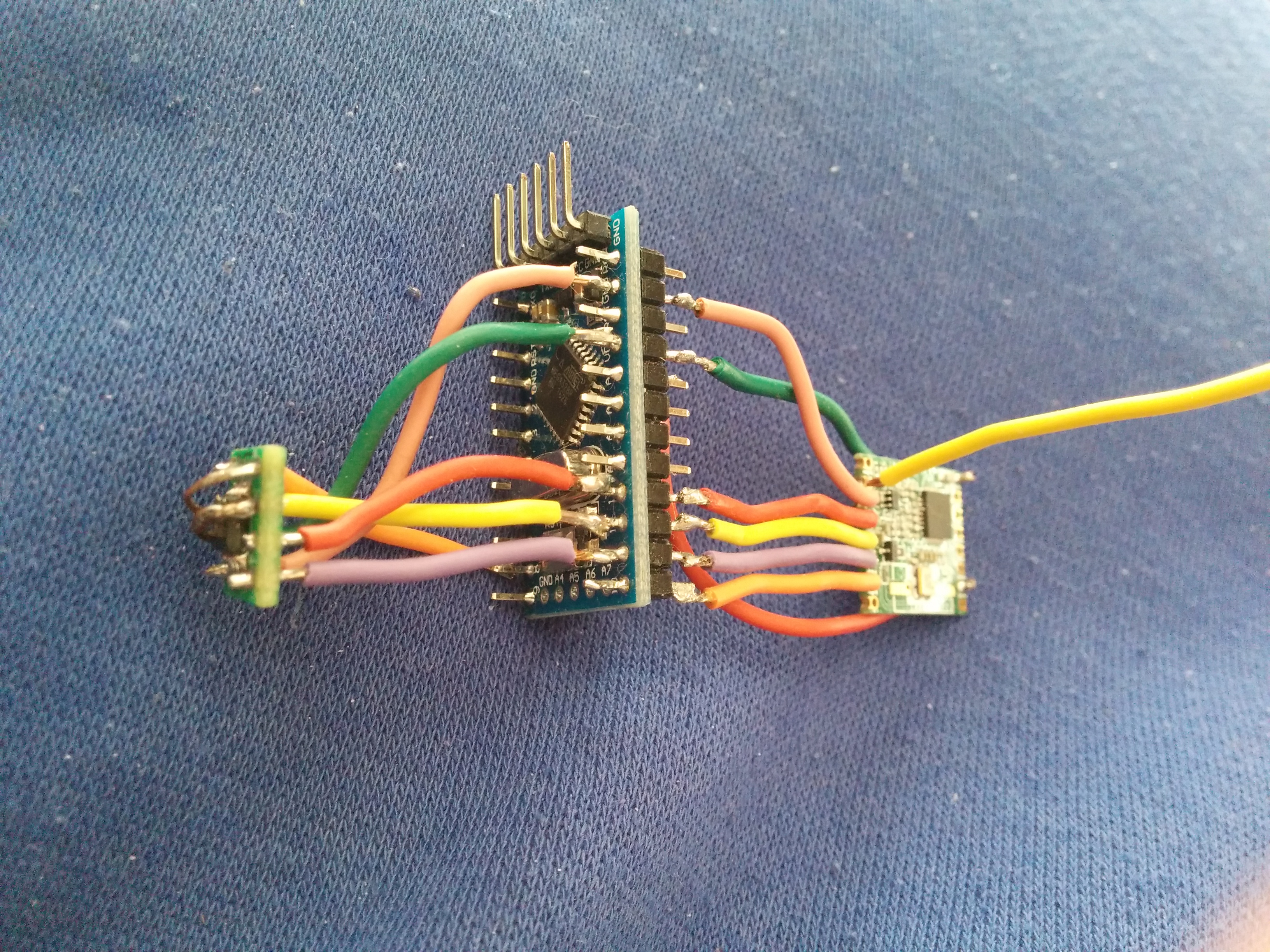
Yea, next to Moteino, this looks horrible, I know! 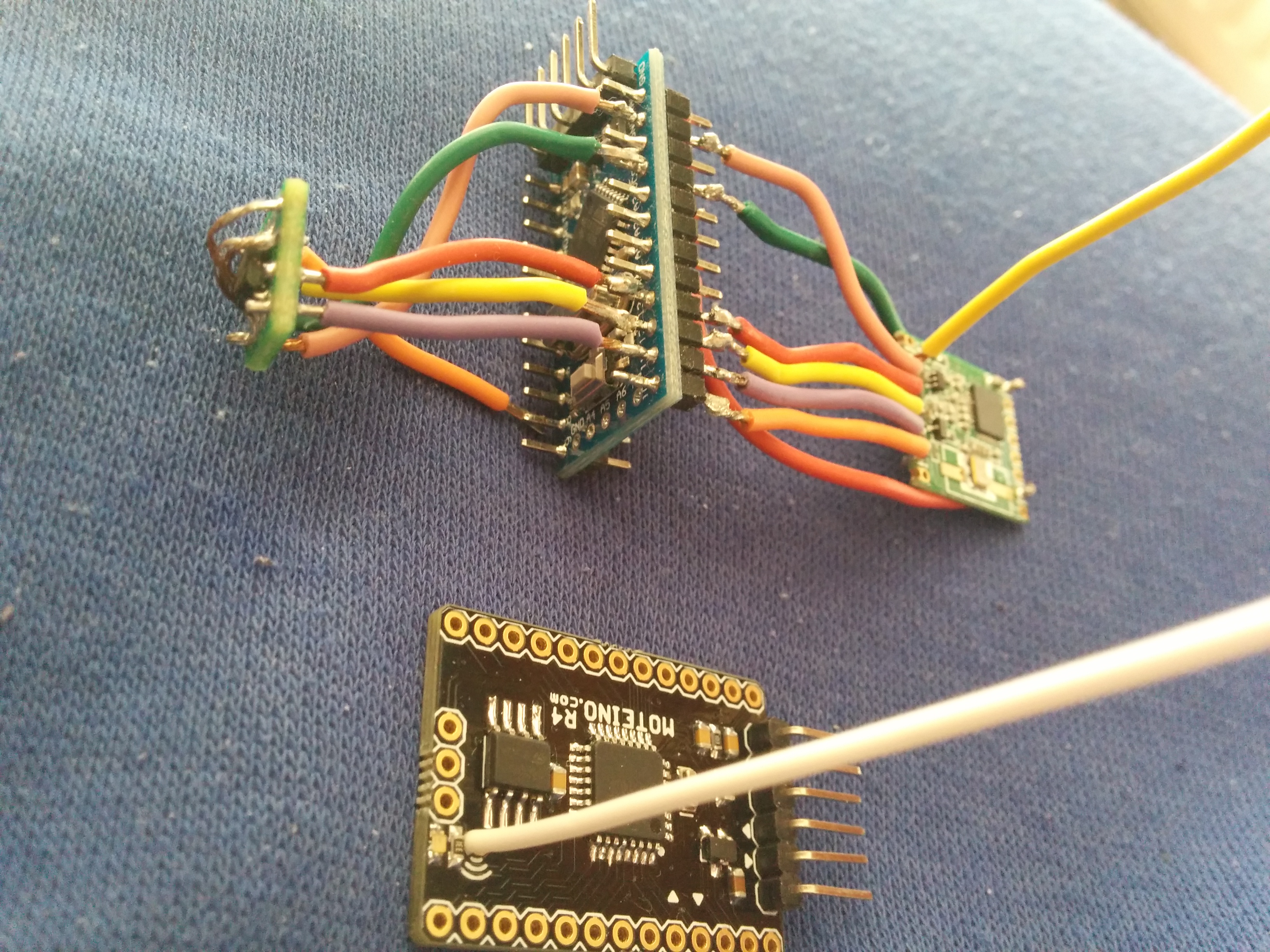
Second attempt was some what better. Plan was to have sensor such as BME280 or SI7021 next to it, but the size would be much bigger. Also was great to experiment with, in this version I tried PCB dipole antenna + coax cable. 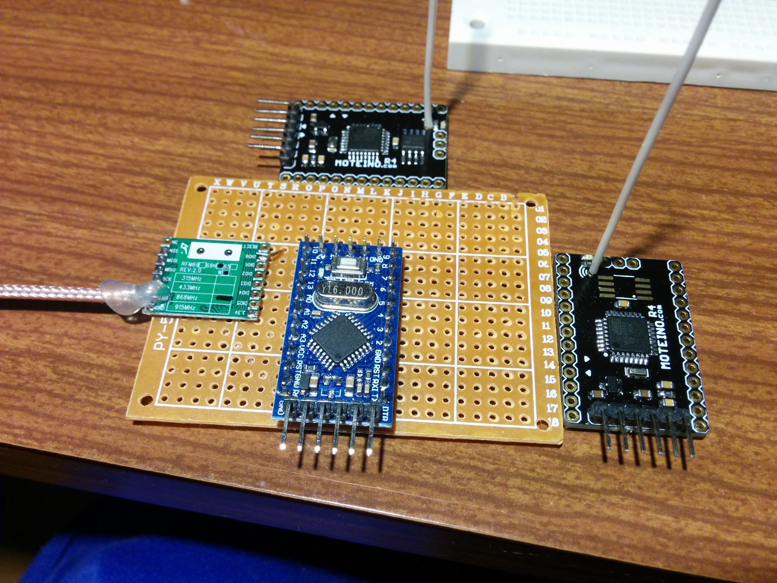
Connections were clean, I liked this approach, despite the increase in size. But in the end, can't compare to Moteino from lowpowerlab.com
Build guide visits: |
|
Application Note on bridging audio amplifiers
A discussion on bridging audio amplifier circuits like LM3886. Includes a schematic to drive a matched pair of amplifiers in a bridged configuration, power supply considerations for LM3886 and TDA1514 power amplifier circuits-especially in bridged pairs. |
Application Note on parallel-bridging LM3886 audio amplifiers
How to make it loud - real loud. (230 watts rms into 8 ohms without clipping from 4 ICs. How to match LM3886s for parallel operation, then bridge the matched parallel banks. If you are not familiar with bridging amplifiers (BTL configuration), read the Application Note on bridging listed left in article Application Note on bridging audio amplifiers. |
| My first car audio system My second car audio system My third car audio system |