LM2576Ok so after "losing" adjustable power supply I needed new one. Only thing I wanted this time was, it wouldn't be linear, coz of heat generated when driving low loads at high current. So I found LM2576, with price of 3� here was something I was happy with, but maybe not as much, coz it is such small device(TO220 with 5 pins). But when you look into its datasheet you see how simple design can be, this means most of the components are inside that small device! GREAT!! So what you need is input and output capacitor, inductor and diode and that it!
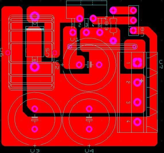
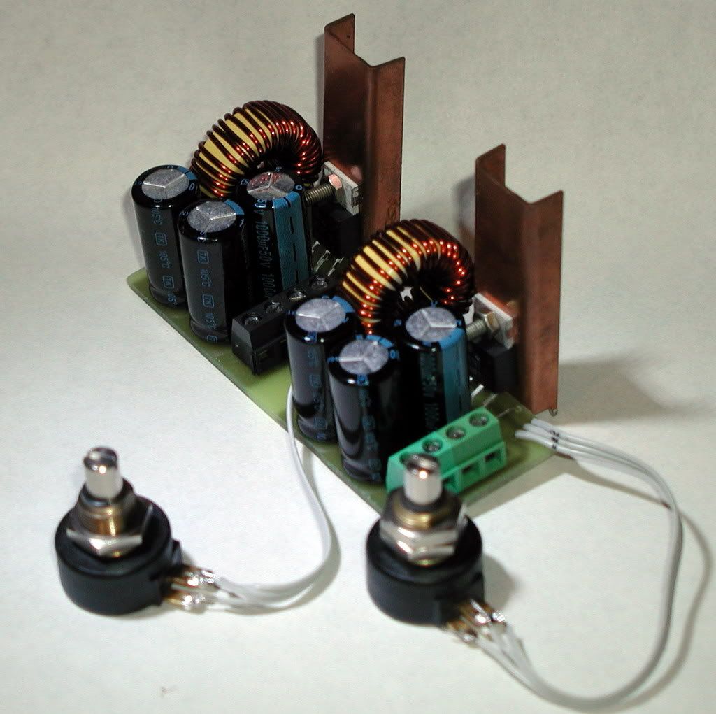
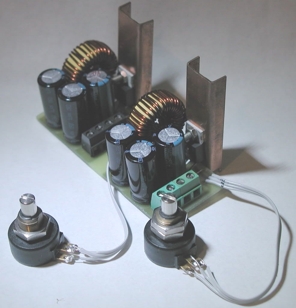
now this is for fix voltage, one that is ADJ has no R1 and R2 inside it, but outside it, right on output. Feedback was done with pot, one side connected to output, one connected to gnd and middle connected to pin 4 of IC. I made inductor myself, used some unkown toroid core, probably from some old PC psu, tried first short wire, just few turns, then longer, and then decidet on somewhat longer, and I end up with 74uH measured, thanks to new LCR meter I got this year. Now it should be 100uH but I think it won't be a problem, wasn't up to now. Test: Ok I have tested it, with 31Vdc, and output can be anywhere from 1.234v (thanks to my new voltmeter that I've also got this year) to over 28v. Now I have some unused 330AV toroid transformer, that gives 44v idle, which is 4v too much. I will see what I'll do with this, probably unwind few turns to get 40v. But what was most fun about this project is how I made PCB, with modded laminator and laser printer. I tell you, from computer to PCB ready to be soldered (holes too) in less then 30min, no sprays, no UV light, ... I will show that project too, HERE (not done yet) I will add pictures to as soon as I add second channel. Board size is only 89mm x 44mm, with about 10mm in between two supplys for screws.
Last fix: I took of first inductor, remove wire of it to see how long wire I will need. so after winding both inductors I measured them any they are both 100uH dead on, put them back on board and thas it. Dual supply done!
PCB in PDF here |
|
Application Note on bridging audio amplifiers
A discussion on bridging audio amplifier circuits like LM3886. Includes a schematic to drive a matched pair of amplifiers in a bridged configuration, power supply considerations for LM3886 and TDA1514 power amplifier circuits-especially in bridged pairs. |
Application Note on parallel-bridging LM3886 audio amplifiers
How to make it loud - real loud. (230 watts rms into 8 ohms without clipping from 4 ICs. How to match LM3886s for parallel operation, then bridge the matched parallel banks. If you are not familiar with bridging amplifiers (BTL configuration), read the Application Note on bridging listed left in article Application Note on bridging audio amplifiers. |
| My first car audio system My second car audio system My third car audio system |