Measuring ESR with function generatorSince I got function generator, I've been dying to try it for measuring internal resistance of capacitors, their ESR. I had about 10 PC power supplys, that were all bad and were discarded. I took them for their elements. Which means there were a lot of different capacitors from which I had no idea, how good or bad they were. Many of them had 105° rating, writen "low esr" also. Since they were also used, I had no way of knowing, which were bad or in good working condition. Before we get to example, you must be reminded, that most function generators have 50R output, this will form RC with capacitor on output. And with that, you have two thing to keep in mind. First would be that if you have some fixed voltage/freq. sine and freq. is still so low, that capacitor at that freq. won't appear to be a short, capacitor will be able to track the voltage on output of function generator. You don't want that. That is problem if capacitance for that frew is to low. So you must choose high enough freq. so that this won't happen. And you don't want to go too high with freq also, since all wires, leads,.. will act as inductor and drop voltage on them. That means to you, that your source voltage is not constant on DUT Second thing would be, R and C form R and R(esr), when freq is high enough, that C is shorted, but not high enough, that L in capacitor starts to have high impedance. Ok let's see picture first, from Wiki: Equivalent circuit
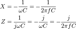
From here you see, that Z or impedance is defined as 1 over 2*pi*freq.*capacitance in Farads This is simplified equation, since most elements are far more complex, even capacitor, this, next model would what you could think of capacitor and wouldn't complicate model too much.
You can omit Rleakage since this R is huge and comes into play with low power DC circuits. Now you have only RCL and since we won't use high freq., L will be almost perfect short and you are left with only RC as above. So here is one example, what you can expect to see: First scope and FG setup.Function generator setup:On FG you wish to set some amplitude, some freq. and DC offset. Ok nothing specific here and why offset? Well for voltage, use few volts p-p if you are doing this outside of a circuit, if in circuit, you must use low enough voltage, that none of active elements will work, something like diode, so lets say 0.2Vp-p. This is still far below and PC juntion voltage. For freq. you could use something like 1kHz for bigger >100uF capacitors, higher if capacitors are smaller. Since I had bunch of 1uF, 2.2uF and so on, up to 1000uF caps, I used 10kHz, since this freq. would be still high enough for 1uF to be seen as short. Offset is needed if you have polarized capacitor, since you shouldn't apply negative voltage to it. Scope setup:As above you set it in such way, that you can see few cycles. DC offset and ampliture used.
Scope is then switched from DC to AC, since we are interested only on AC part of signal.
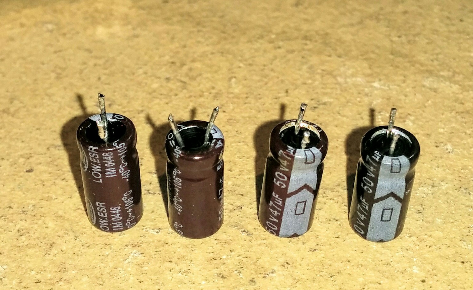
Now we are ready to measure Here are 4, 47uF capacitors, which were pulled out of those PC power supplys.
They all look ok, 3 of them are the same brand and model. And here are measurements. First I will show you, how good capacitor should look, for this freq. and voltage of output signal. It is more of a relative measurement, to compare on cap to another. But in any case, you can see ESR, how is affected between same caps. The best cap, showed only 35mVpp voltage on it, which would mean, very low ESR, since most of the voltage is dropped insice FG on that 50R, almost all of the 2V it was set with open circuit. So great, good cap.
This would be still a good cap, but you can already see, that is has higher ESR, while both caps read the same capacitance on RCL meter. So higher ESR on this cap, but still ok to use if you ask me.
Here is perfect example, because if it, I even wrote this page. On this last one, you can see that it drops almost ALL voltage, that means that ESR of this cap is MUCH higher then output resistance of FG, so MUCH higher then 50R. Still visually it looked perfect. But also on RCL meter it showed capacitance of something like 26nF, which if far off 47uF rated, 39uF measured capacitance on others.
ESR is good indicator, what is going on with it, since it can measure ok for C, it could already start to show its are or future failure, since higher ESR means more heating of capacitor when they are used in switching aplication. On the side note, none FG parameters were changed when testing different capacitors, this way you get good idea, how they compare one to another for this freq. ESR visits: |


|
Application Note on bridging audio amplifiers
A discussion on bridging audio amplifier circuits like LM3886. Includes a schematic to drive a matched pair of amplifiers in a bridged configuration, power supply considerations for LM3886 and TDA1514 power amplifier circuits-especially in bridged pairs. |
Application Note on parallel-bridging LM3886 audio amplifiers
How to make it loud - real loud. (230 watts rms into 8 ohms without clipping from 4 ICs. How to match LM3886s for parallel operation, then bridge the matched parallel banks. If you are not familiar with bridging amplifiers (BTL configuration), read the Application Note on bridging listed left in article Application Note on bridging audio amplifiers. |
| My first car audio system My second car audio system My third car audio system |