|
This active PFC was build around MC34262. Circuit is really simple and easy to understand, only few components are needed. 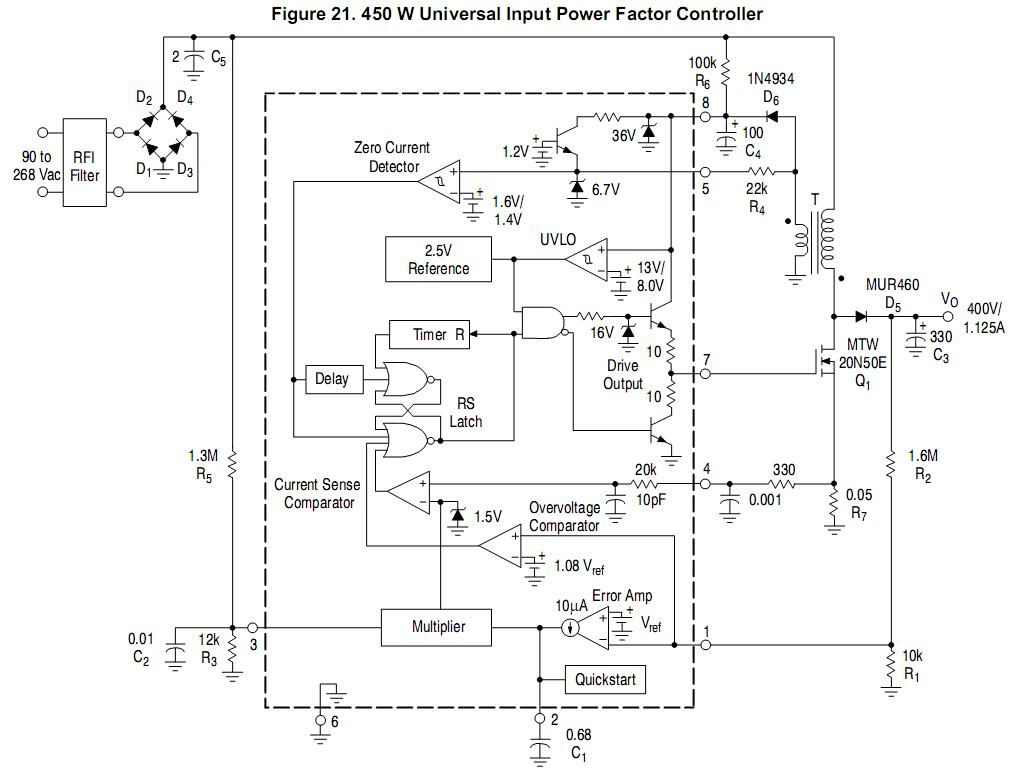
I didn't use all the same values as here, coz I didn't have them and some setting wanted diffrent, such as output voltage. So in this case R7 for start is 0.22, I'll maybe add a nother one, same size Also R5 is not 1.3M but 1.2M in my case, shouldn't make much diffrence C1 was 330nF, I used this value coz I got capacitor from some board that has had parts for this PFC on it, like IC, inductor,.. Inductor, what I can tell about it is not number of turns for it, coz it was already assembled, but I have measured inductance to be 120uH, and secondary winding gives 22Vdc with 235Vac, where max voltage is 330Vdc... So I guess you can get ratio from here. For fet I used Irfp450, doesn't get even warm. For output diodes I used Mur4100, and that is because I couldn't get Mur460. I will probably changed them. I have 2 of them, but place on pcb is for 4. This is the element that gets most got in this project. Here could be used any fast high voltage diode, but I gone with one that don't need heatsink. For output capacitance I have 2x 220uF 400V caps and based on this I have used diffrent feedback resitors. I used 1.2M + 330k and lower resistor (R1) is the same, 10k. R6 should be 100k, I used 220k, but I think I will change that also, down to 100k, since it takes now say 4s before pfc starts. For D6 you can use any fast diode with rating say 1A or so, really no current going through it, but it has to be fast and has to block voltage >22V in my case. I used byv10-40 which I had laying around for some time. Oh yes, one more thing, about inductor, its size: It is like ETD44, core is 19.5mm wide, 42mm long, and 21mm tall, and has cross of about 2.3cm^2. Gap is unknown, but should be known if inductance is known. I have done some tests, diods were pretty much most limiting part here, heating up fast, also input bridge rectifier is I think only 4A so I didn't go past this, but I have measured 760w on ouput, with voltage always steady on 387Vdc. Only thing bad about this IC is its overvoltage protection, which is 8% higher then feedback. So this means with light or no load, output voltage will be going over 400V...I should have 450V rating on caps, but what can you do.. :D Tested to over 1kw for few seconds, but would need better diods for longer period of load Pictures and PCB still to come..
Pfc visits: |
|
Application Note on bridging audio amplifiers
A discussion on bridging audio amplifier circuits like LM3886. Includes a schematic to drive a matched pair of amplifiers in a bridged configuration, power supply considerations for LM3886 and TDA1514 power amplifier circuits-especially in bridged pairs. |
Application Note on parallel-bridging LM3886 audio amplifiers
How to make it loud - real loud. (230 watts rms into 8 ohms without clipping from 4 ICs. How to match LM3886s for parallel operation, then bridge the matched parallel banks. If you are not familiar with bridging amplifiers (BTL configuration), read the Application Note on bridging listed left in article Application Note on bridging audio amplifiers. |
| My first car audio system My second car audio system My third car audio system |