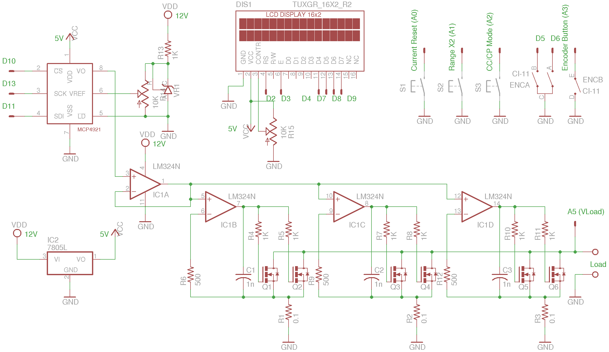
Arduino electronic loadAfter looking on the web for some time, I have found site from Kerry D. Wong, where he has many nice projects. One of them being this one. Looking and reading all about it, I was impressed and started looking for parts needed. Since I could get them, I decided to go ahead and start building it on breadboard. For the brains as in all of the project I used Arduino Pro Mini off the Ebay, since it is so cheap, I couldn't be bothered to build one myself. Schematic:
First I made just basic circuit, that most people use, fully analog, since it is the heart of this project. If you look at the circuit around operational amplifiers (LM324), IC1A is buffer between DAC and other OP amplifiers. it is used to provide low impedance drive for all stages. So this one is needed and also one that will drive the fet. And to make things simple, only one fet was used. Since normally reference voltage on + of the IC1A comes from DAC, I had to provide one myself, which come of multi turn pot, which was set to 0v, as you don't want huge current to flow the first time you turn it on (+ input of IC1A connected to GND). Let me make a HUGE note right here: solderless Plug-in breadboard are pretty bad for testing this type of things, since we are dealing with very low voltages in <100 mV range. First test showed that minimal current that could be sink was around 60mA (which only later was discovered that it can be half that). I already like it very much. Then I got MCP4921, which is 12bit DAC with external reference (which is used to set max current that this load could sink). And since everything was already written for Arduino, by mr. Wong, I changed few things to suit my needs, like using I2C lcd over the standard interface. That also left me with many unused pins. I also moved some key from analog port to digital, since I might use then to sense something else, like temparature and drive PWM fan or something.. Original plan was and is, to use this load to maybe test even PFC at almost 400v, but that will have to wait and see if I'll go for that. I know mosfets are fine for those voltages. But non of the "cheap" electronic loads I've seen, were able to sink current at 400v. Well that is not true, there are, but they cost almost 2000$. Second step was to move from breadboard to some what finished board, but not something like normal watched pcb. I had one of those cheap perforated boards, on to which I could fit everything,.. at least what would be mounted on case itself, like rotary encoder and buttons. I also give opa4340 and opa340 a try, since they were able to go down to 1mV on output, which is far better then LM can. But first time under power, there was no change. Again around 30mA minimal current. then I tryed something, which I didn't think it would do anything. Arduino Pro Mini board have two (3 if you count comunication port) GND pins, one across each other. One was already connected to 0.1R current sense resistor (which was at that point still on breadboard), where all point od connection for GND were. And what do you know, current went down to 17-18mA. This means (and I checked), you could drive normal led without any current limiting resistor (apart from ELoad being instead of it), and on 35V+ supply! Looking at different nodes on board with scope, like anything between DAC and mosfet shows, there was a lot of noise, some from the circuit itself, some from external supplies and a lot from AC line. Which also put me into direction, where I started to look for line filter. Operating at such low voltages, noise is the one and almost the only enemy. You HAVE to understand, that with this values for components, 1mV is equal to 10mA on output.
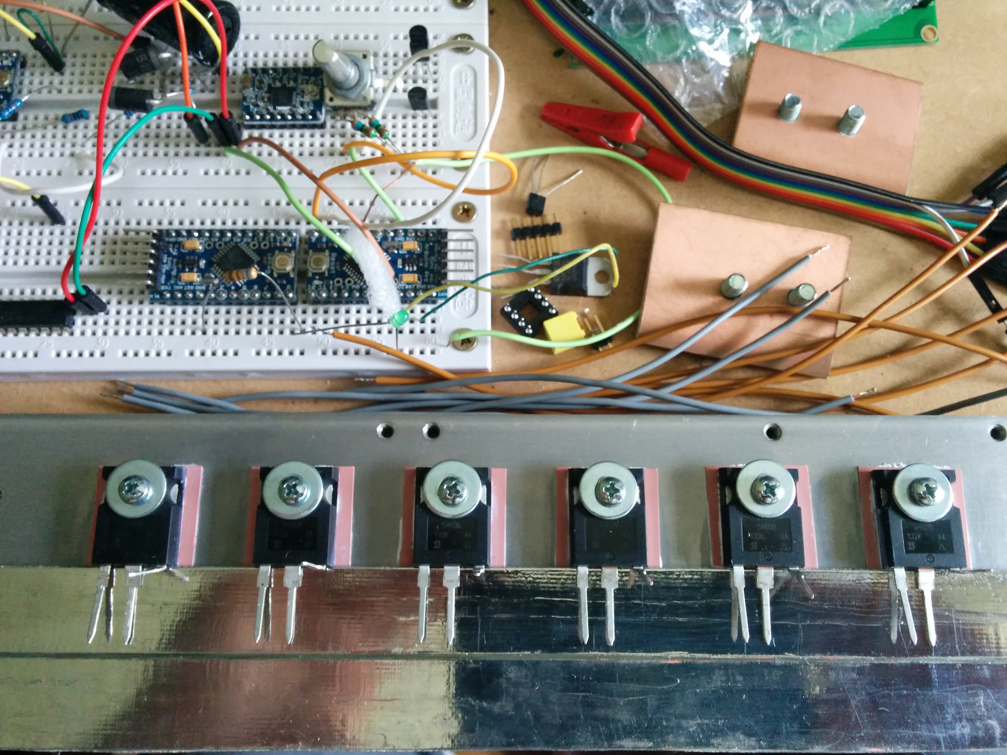
The buildHere are some picture of final build process, what I was thinking and so on Idea was to use what I had laying around and would be nice to use for something great and not random as most od the times.
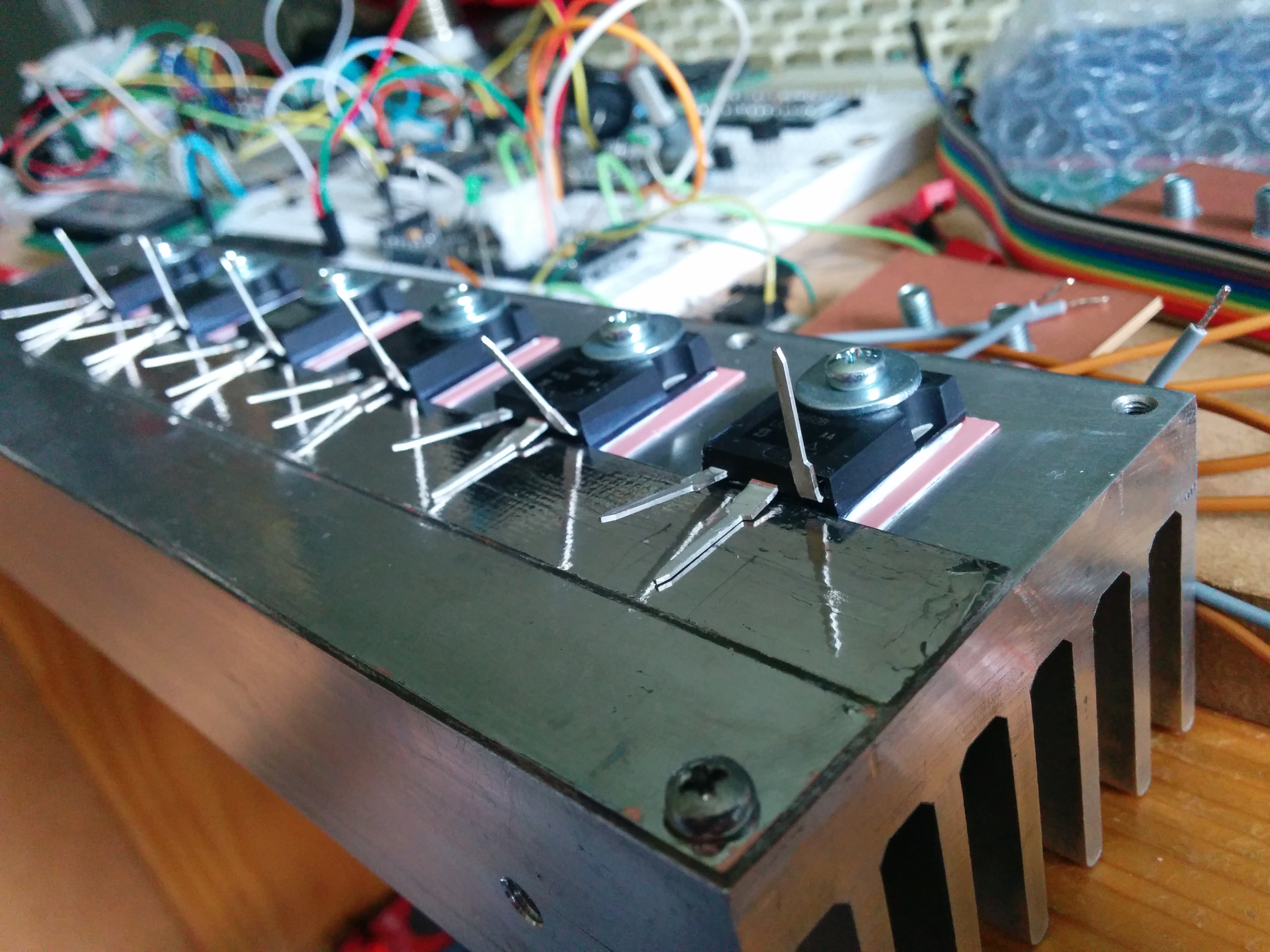
I had this heatsink for some time, I would just fit into the case I also had. I all I had to do is drill and tap few holes for fets, which were spaced one mosfet apart (3 fets next to each other, then removed middle one). Below them, there is simple pcb, just to make thing more simple and less wires are used, more neat.
Legs bend up, which would go to sense resistor. Middle one is soldered and gate would be isolated and "floating" on wire directly Another view
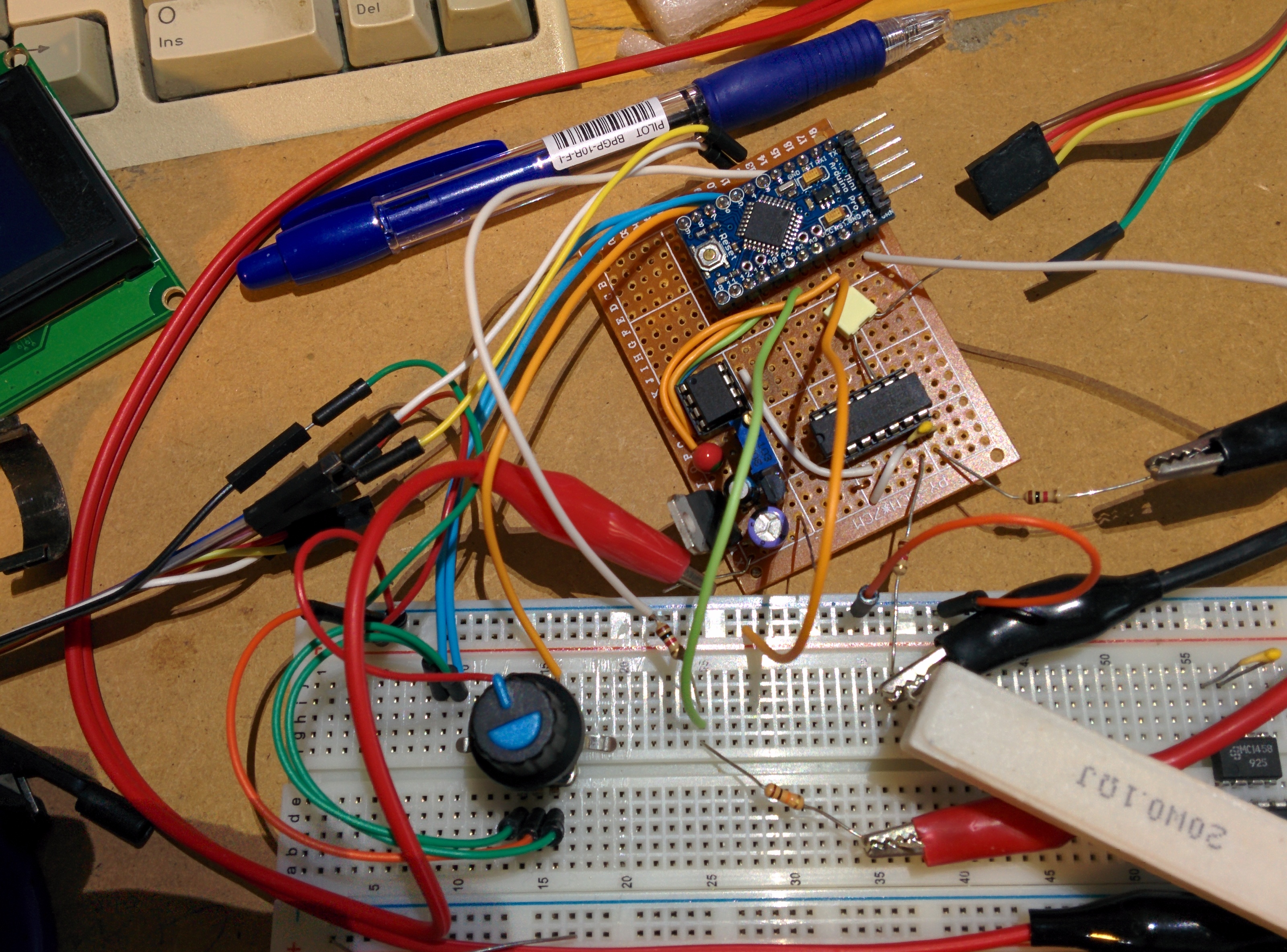
Control logic: Small board with important IC and other bits and bobs on it. The brain of it all. It's input is encoder with which you set all different settings and modes. They are displayed on LCD via i2c (apart from one more library, there are only 3 wire, another thing, which makes case less cluttered). ELoad visits: |

|
Application Note on bridging audio amplifiers
A discussion on bridging audio amplifier circuits like LM3886. Includes a schematic to drive a matched pair of amplifiers in a bridged configuration, power supply considerations for LM3886 and TDA1514 power amplifier circuits-especially in bridged pairs. |
Application Note on parallel-bridging LM3886 audio amplifiers
How to make it loud - real loud. (230 watts rms into 8 ohms without clipping from 4 ICs. How to match LM3886s for parallel operation, then bridge the matched parallel banks. If you are not familiar with bridging amplifiers (BTL configuration), read the Application Note on bridging listed left in article Application Note on bridging audio amplifiers. |
| My first car audio system My second car audio system My third car audio system |