|
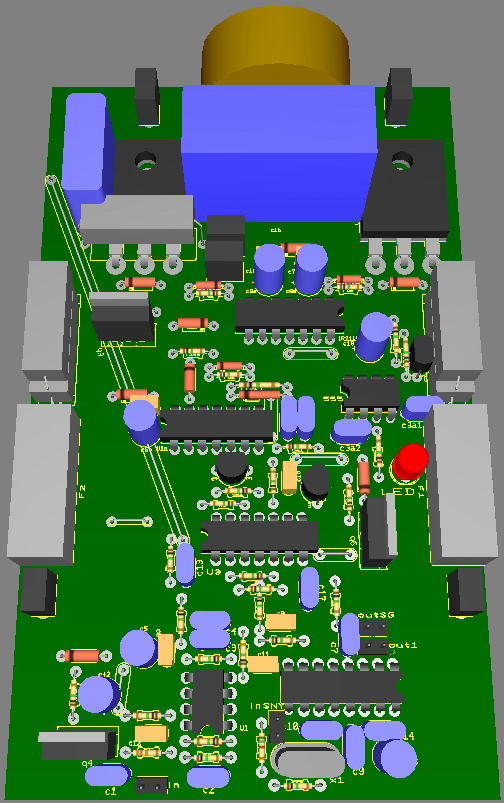
This is how it will look like 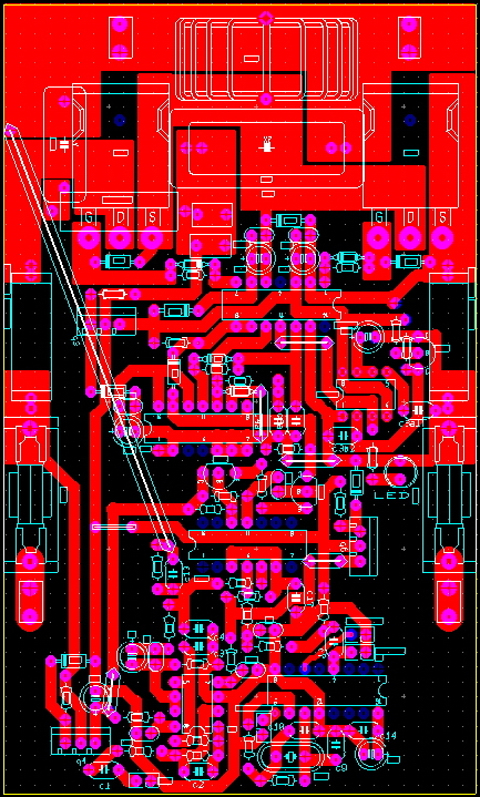
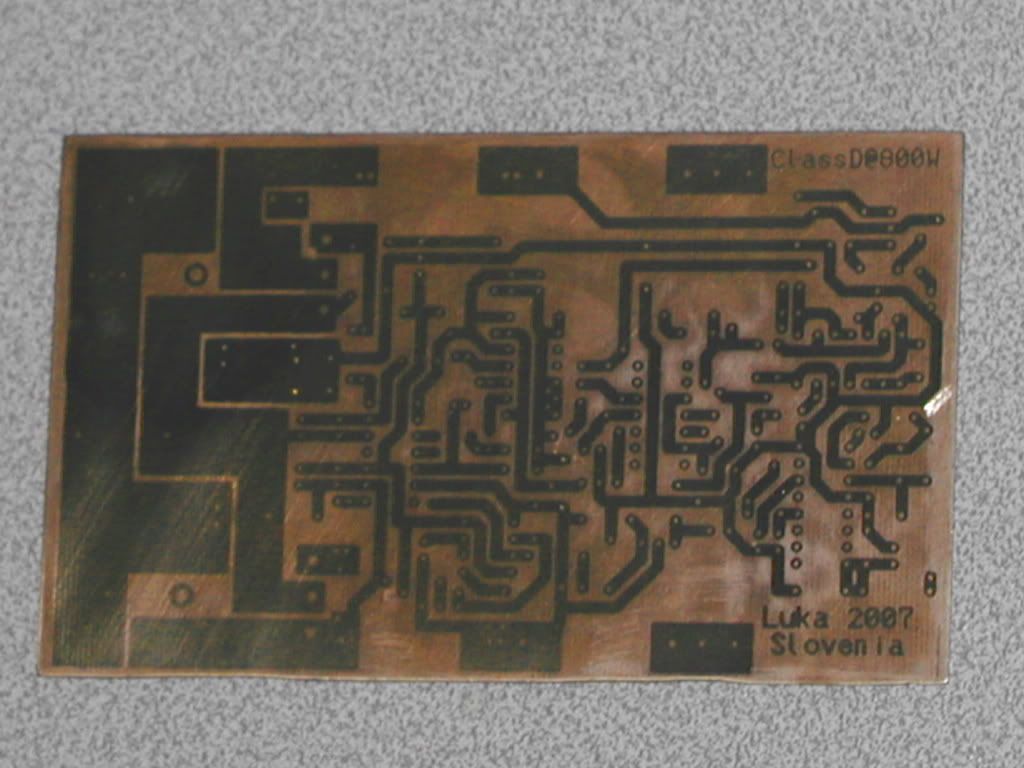
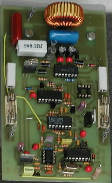
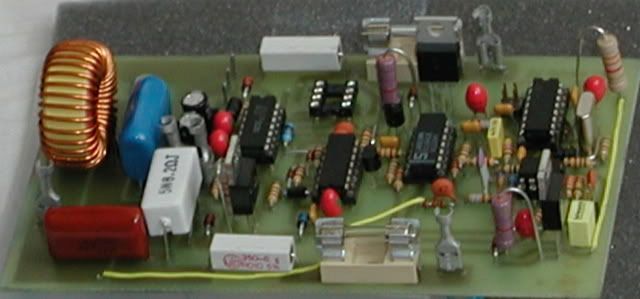
Before eatching...
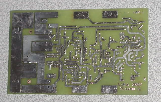
Board after being eatched and ready to put elements on
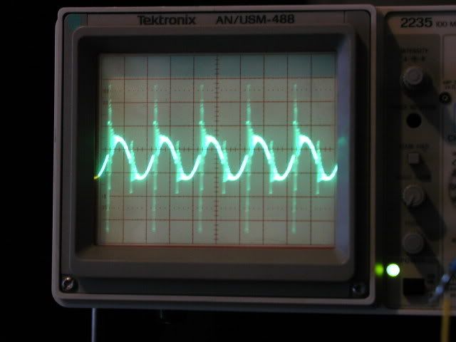
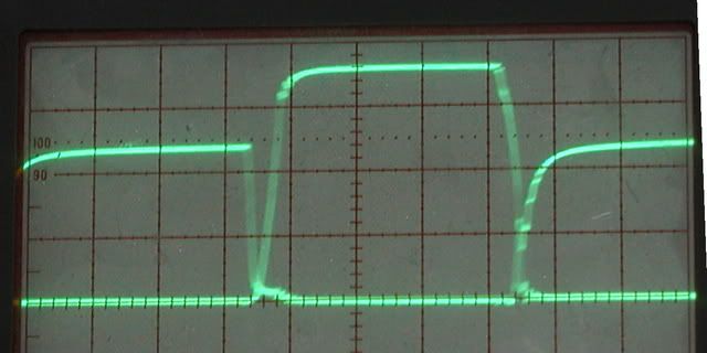
On picture above one can see that one chip is missing.That is overcurrent limit, which becomes active when ther is bigger voltage drop on current sense resistor then set. This activates the timer, which disables output for time that is set by components, which is in my case a bit over 1s. After that output is enabled again. Output ripple @ 250kHz with spikes because of too small cap use to decouple supply.But I have been told that it could be throughshoots (Bigger dead time will be needed). This does NOT effect the sound, but will need to be sorted out for higher efficiency. Sinewave is always present on output in any ClassD amp.This one is 1Vpp and that is small and is dependent of supply voltage, output filter and freq. of the amp.
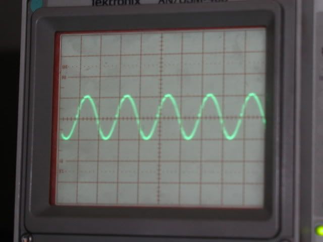
This was caused by usage of wire resistor, which has inductance, that cause this spikes. After swaping them with non-wire ones, this is what came out. Difference is big as seen from pictures up and below
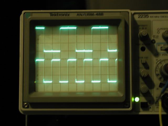
Picture of both gates looking them at the same time. Not the best, but doesn't seem to cause any problems
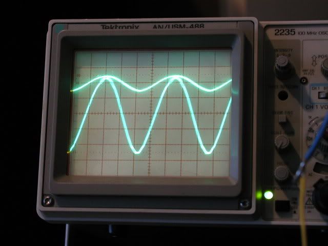
Upper one is input, lower one is output near clipping.
Synchronizing clocks, 125kHz for smps and 250kHz for other amps
Thing to remember: - Use fast fets, which has small Qg (total gate charge), small Rds(on), but most important small trr (Reverse Recovery Time of diode) and for that matter Qrr too. Schematic is here Next page is problems, solutions and what was wrong. |
|
Application Note on bridging audio amplifiers
A discussion on bridging audio amplifier circuits like LM3886. Includes a schematic to drive a matched pair of amplifiers in a bridged configuration, power supply considerations for LM3886 and TDA1514 power amplifier circuits-especially in bridged pairs. |
Application Note on parallel-bridging LM3886 audio amplifiers
How to make it loud - real loud. (230 watts rms into 8 ohms without clipping from 4 ICs. How to match LM3886s for parallel operation, then bridge the matched parallel banks. If you are not familiar with bridging amplifiers (BTL configuration), read the Application Note on bridging listed left in article Application Note on bridging audio amplifiers. |
| My first car audio system My second car audio system My third car audio system |